22 Installation
Fire detection and extinguishant system
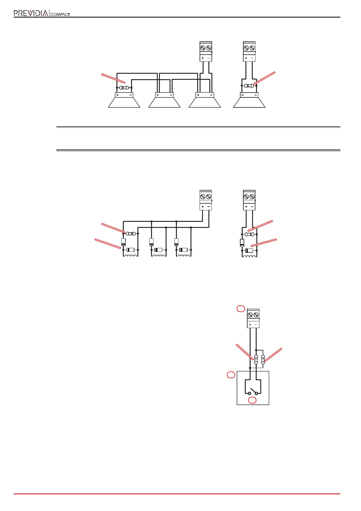
Connection of polarized devices (sounders, etc.) to channels configured as outputs
The polarities refer to the active status of the output, the polarities invert for stand-by status.
EN54:
If the control panel default settings are left unchanged, the I/O 1 output will result as being configured as
a type C output for the connection of audible/visual signalling devices.
The output will activate in the event of any type of fire-alarm condition.
Connection of non-polarized devices (relays, etc.) to channels configured as outputs
The polarities refer to the active status of the output, the polarities invert for stand-by status.
Connection of devices with an alarm output to channels configured as input
The wiring diagram illustrates a connection made to one of
the “I/O” channels [A], configured as input. The connected
device [B] is equipped with a normally open output for alarm
signalling [C].
I/Ox I/Ox
1KOhm - 1W
brown, black, red
1KOhm - 1W
brown, black, red
I/Ox I/Ox
1KOhm - 1W
brown, black, red
1KOhm - 1W
brown, black, red
1N4007 diodes
1N4007 diodes
B
C
A
3K9Ohm
orange, white,
red
470Ohm
yellow, purple,
brown