16 General Description
Fire alarm and extinguishing system
EN12094-1: In compliance with the requirements of standard EN 12094-1, if the “Stop extinction-Abort” function is
used in a Previdia Micro control panel, the “Stop Extinction-Hold” and “Stop Extinction-Add” functions
cannot be activated, and vice versa.
Please remember that no more than 32 devices can be connected to each of the selected input or
output terminals.
2.4 Previdia-C-DIAL, telephone line Communicator module
The optional PREVIDIA-C-DIAL board allows you to connect Previdia Micro control panels to the landline (PSTN) and to
the GSM 2G and 3G networks.
It manages reporting protocols used by alarm receiving centres. This module allows the control panel to make voice
calls and send SMS text messages.
The board comes with:
• Mounting plate
• 7 mounting screws
• cable for the connection to the motherboard
• remote antenna
• Instructions manual
SIM card not included
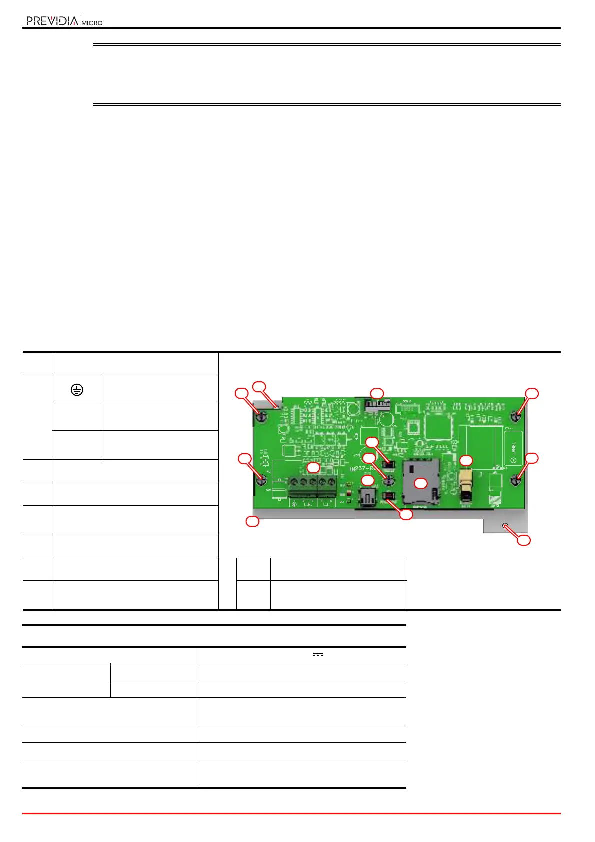
[A]
Motherboard connector
[B]
Ground terminal
L.E.
Telephone line
connection terminals
L.I.
Internal telephone line
terminals
[C]
Mini USB port
[D]
Reset button
[E]
Button to reset default settings
(factory settings)
[F]
SIM card holder
[G]
GSM antenna connector
[I]
Mounting plate
[H]
Screws for fixing the board to the plate
[J]
Hole for the mounting plate
screw
Technical specifications
Power supply voltage 19-30 V
Consumption @
27.6V
stand-by 40mA
maximum 140mA
Band frequency
2G: 850/900, 1800/1900 MHz
3G: 800/850/900, 1900/2100 MHz
Maximum RF output power 2W, 1W
Operating temperature from -5°C to +40°C
Antenna
remote GSM-UMTS cable 2m, SMA-Male connector
(50Ohm impedance) and magnetic base