Installation manual
Installation 31
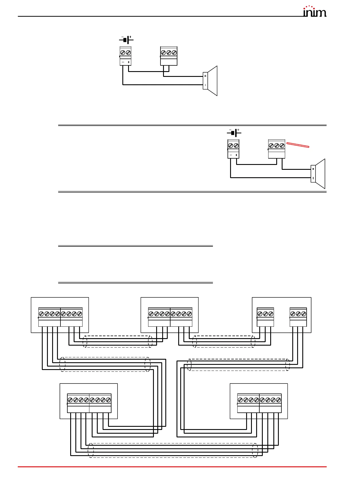
The relay output of the module (terminals “28-29-30”) must be connected according to the following diagram:
All voltage free relay contact can only be connected to SELV circuits.
The illustrated connection does not supervise the cable and does not signal connection faults.
EN54: If the control panel default settings are left unchanged,
the RELAY output will result as being configured as a
fault signalling output.
In compliance with the regulations in force, the output
must be configured as “inverted” in order to switch to
fault condition when the system is completely without
power.
Therefore, in stand-by status (no faults present on the
system) terminals C and NO will be closed, whereas
terminals C and NC will be open.
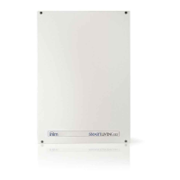
3.7 Connecting the Hornet+ network
The connection of two or more control panels (Previdia Max, Previdia Micro or repeaters) in a Hornet+ network can be
achieved by using two RS485 communication ports.
Cables: 4 wire shielded cable
Typical impedance 12Ohm
Maximum length 1000m (between two successive control
panels)
Compliant with local laws and regulations in force
21 3
A+
-
A-
4
+24
65 7
B+
-
B-
8
+24
21 3
A+
-
A-
4
+24
65 7
B+
-
B-
8
+24
21
Port-A
3
D-- D+
21
Port-B
3
D-- D+
21 3
A+
-
A-
4
+24
65 7
B+
-
B-
8
+24
21 3
A+
-
A-
4
+24
65 7
B+
-
B-
8
+24
Previdia Micro
Previdia Micro
Repeater
Previdia Compact REP
Previdia MaxPrevidia Micro