Installation manual
Installation 29
3.5 Connection of function inputs and outputs
The Previdia Micro control panel and the PREVIDIA-M-EXP module provide the following terminals for connection of
devices configurable as input or output function:
Cables: 2 wire shielded cable
Proper section (minimum 0.5mm², maximum 2.5 mm²)
Compliant with local laws and regulations in force
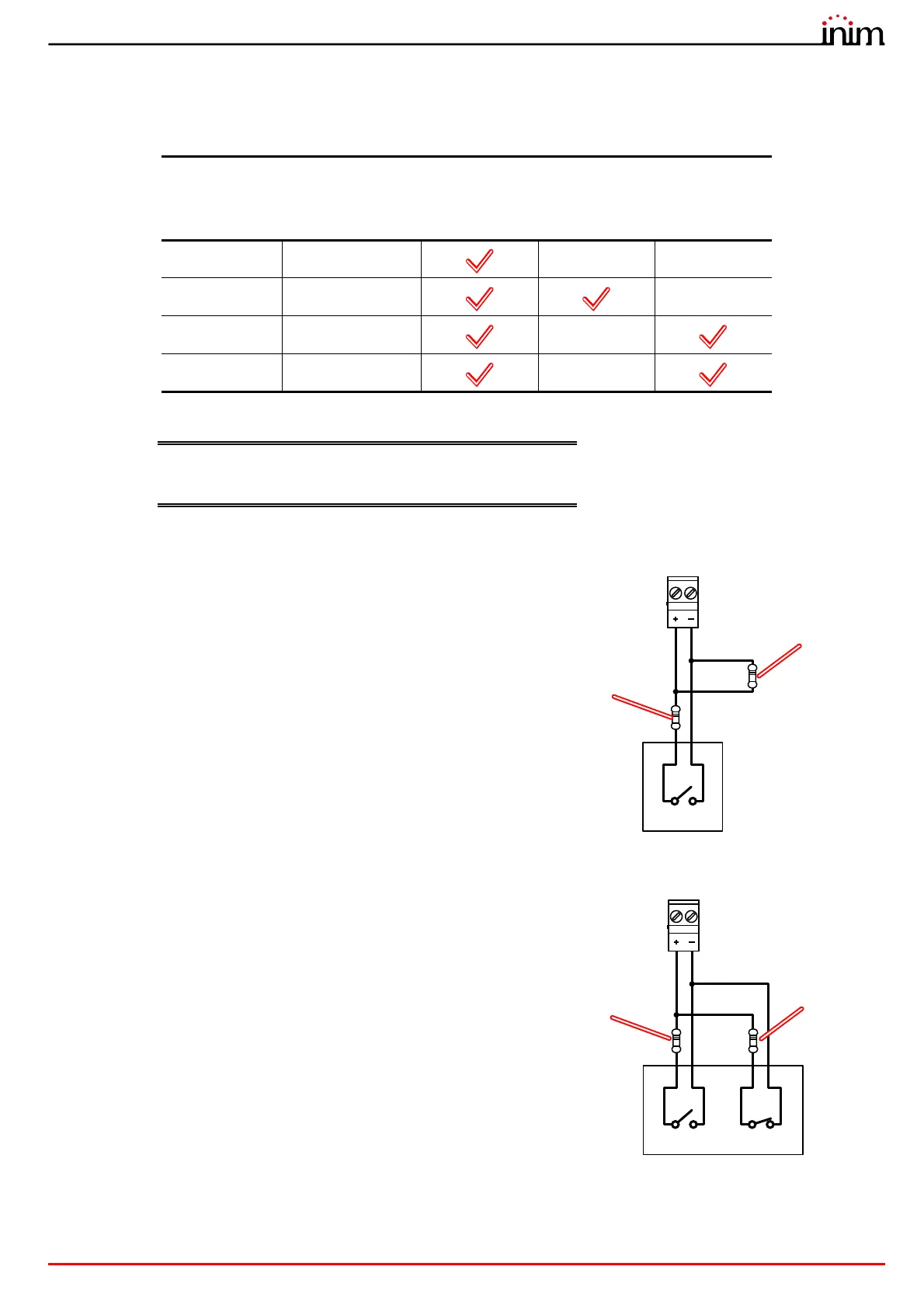
Connection of devices with alarm signal
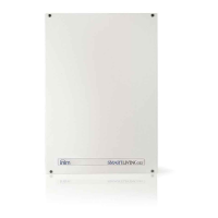
Connection of devices with alarm and fault signals
Terminals
Inputs
Outputs
Previdia
Micro
PREVIDIA-M-
EXP
100 mA 1A
L1, ... L4 LINE1, ... LINE8
/ /
T1, ... T4 T1, ... T6
/
I/O1, I/O2 I/O
/
AUX
/ /
The wiring diagram illustrates a connection to be made to one of the
Lx, Tx, I/Ox or AUX terminals configured as input.
The connected device is equipped with a normally open output for
alarm signalling.
The wiring diagram illustrates a connection to be made to one of the
Lx, Tx, I/Ox or AUX terminals configured as input.
The connected device is equipped with a normally open output for
alarm signalling and a normally closed output for fault signalling.
3K9Ohm
orange, white,
red
Lx / Tx / I/Ox / AUX
Alarm
330Ohm
orange, orange,
brown
3K9Ohm
orange, white,
red
Alarm Fault
Lx / Tx / I/Ox / AUX
330Ohm
orange, orange,
brown