28 Installation
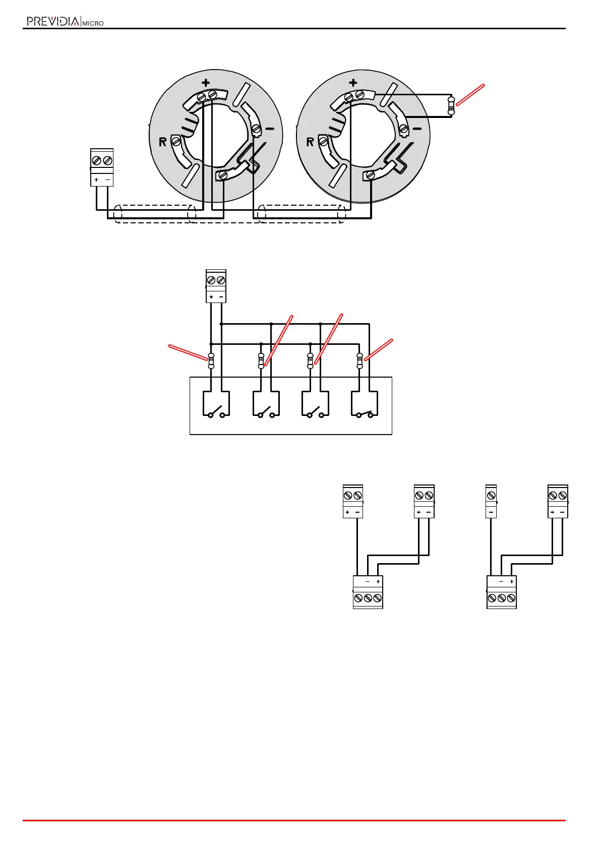
Fire alarm and extinguishing system
Connection of smoke detectors
Connection of relay gas detectors
Connection to channels configured as 4-20mA gas input
The wiring diagram illustrates the connection to be made to
one of the Lx or Tx terminals configured as gas input to which
is connected a generic 4-20mA output device powered from a
24V source, in the diagram the control panel AUX terminals.
Detector
3K9Ohm
orange, white,
red
Lx
Detector
3K9Ohm
orange, white,
red
Lx / Tx / I/Ox
Alarm Prealarm Early Warning
2K2Ohm
red, red, red
Fault
1KOhm
red, black, red
330Ohm
orange, orange,
brown