22 Installation
Fire alarm and extinguishing system
3.2 Mounting of the PREVIDIA-C-DIAL, PREVIDIA-C-COM and PREVIDIA-M-EXP
optional modules
The PREVIDIA-C-DIAL, PREVIDIA-C-COM and PREVIDIA-M-EXP modules must be mounted
inside the cabinet.
Attention: The module installation procedure must be carried out after disconnecting
the control panel power supply (220V and batteries).
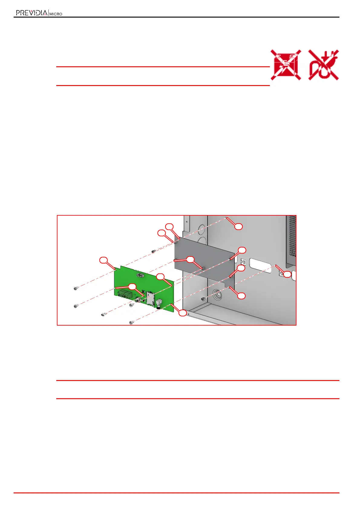
Single module
If only one of the optional modules is to be installed, the procedure to be followed is as follows:
1. Open the control panel cabinet by removing the metal front plate and the plastic support of the motherboard
(paragraph 2.2 - [P]).
2. Attach the mounting plate to the back of the cabinet by fastening the screws provided into the appropriate holes ([A],
paragraph 2.2 - [Y], paragraph 2.4 - [J], paragraph 2.6 - [F]).
3. Attach the board to the mounting plate by fastening the screws provided into the appropriate holes ([B], paragraph
2.4 - [H], paragraph 2.5 - [L] and paragraph 2.6 - [G]).
4. Using the cable supplied, connect the module to the motherboard via the appropriate connectors (paragraph 2.2 -
[M] and paragraph 2.4 - [A] for PREVIDIA-C-DIAL, paragraph 2.2 - [N], paragraph 2.5 - [A] for PREVIDIA-C-COM and
paragraph 2.6 - [A] for PREVIDIA-M-EXP).
5. Complete the external connections.
6. Replace the plastic support and replace the lid.
More modules
If several optional modules are to be installed, the procedure is as follows:
1. Mount the first module on the back of the cabinet following the procedure described above.
Previdia Micro control panels in large cabinets provide two positions on the back of the cabinet (paragraph 2.2 - [Y]).
Note: If you are also installing a PREVIDIA-C-DIAL module, this must be positioned as the first module on the
back of the cabinet.
2.
The successive module must be mounted to the first.
Attach the spacers supplied with the second module to the mounting holes of the first module (
[C]
,
paragraph 2.4 - [H]
and paragraph 2.5 - [L]).
For PREVIDIA-M-EXP modules (paragraph 2.6 - [G]) the holes are different from those for mounting to the back of the
cabinet.
3. Attach the second module to the spacers by fastening the screws provided into the appropriate holes
(
[D]
,
paragraph
2.4 - [H] and paragraph 2.5 - [L], paragraph 2.6 - [H]).
4. Using the cable supplied, connect the module to the motherboard via the appropriate connectors (paragraph 2.2 -
[N] and paragraph 2.5 - [A]).