Installation manual
General Description 9
Chapter 2
General Description
2.1 Previdia Micro Models
Previdia Micro is a series of control panels for the management of fire detection and extinguishing systems.
This series provides different models of control panels distinguished by the type of cabinet in which the modules are
housed, the presence of signalling LEDs on the front plate and the possibility of managing an extinction channel.
The name of each model specifies its characteristics, in accordance with the following table:
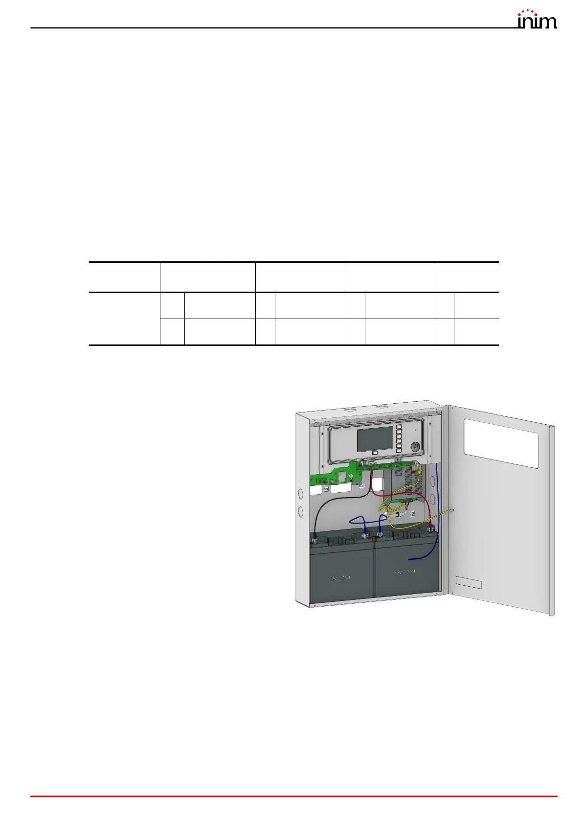
2.2 Control panel descriptions
Each control panel model comes in a metal cabinet that is
packed in a cardboard box. The cabinets used for the
Previdia Micro series differ in size and colour:
• small cabinet, dimensions 325x325x80mm, capacity to
house 2 batteries of 1,5A – 7Ah, in light grey or red
• large cabinet, dimensions 497x380x87mm, capacity to
house 2 batteries of 4A – 7Ah, in light grey or red
Installed inside:
- CPU unit with 4.3’’ touchscreen, buttons and LEDs for
the user interface
- I/O unit for the management of the lines of the
Hornet+ network and input/output terminals
- power supply module
- batteries, not included
In Some versions there is also a signalling module with 30
individually programmable indicator LEDs (three colours).
The modules can be installed in all the control panels in
the range:
• PREVIDIA-C-DIAL (communicator module for communications over PSTN or GSM networks and the management of
GPRS connections
• PREVIDIA-C-COM (serial and IP interface module)
• PREVIDIA-M-EXP (8 line detection expansion module)
Supplied with the control panel is a plastic bag containing:
• battery connection wires
• connection wire with accessory board (PREVIDIA-ML only)
• ring terminal for the earth connection
• keys for the selection of access level 2
• resistors and EOL diodes for the supervised circuits
• Installation manual
Series prefix
Mounting cabinet
size
Zone LEDs Extinction channel
Cabinet
colour
PREVIDIA-M
S
small cabinet
Z
Available LED
indicators
E
Discharge zone
G
grey
L
large cabinet
-
LED indicators
not available
-
Extinction not
available
R
red