30 Installation
Fire alarm and extinguishing system
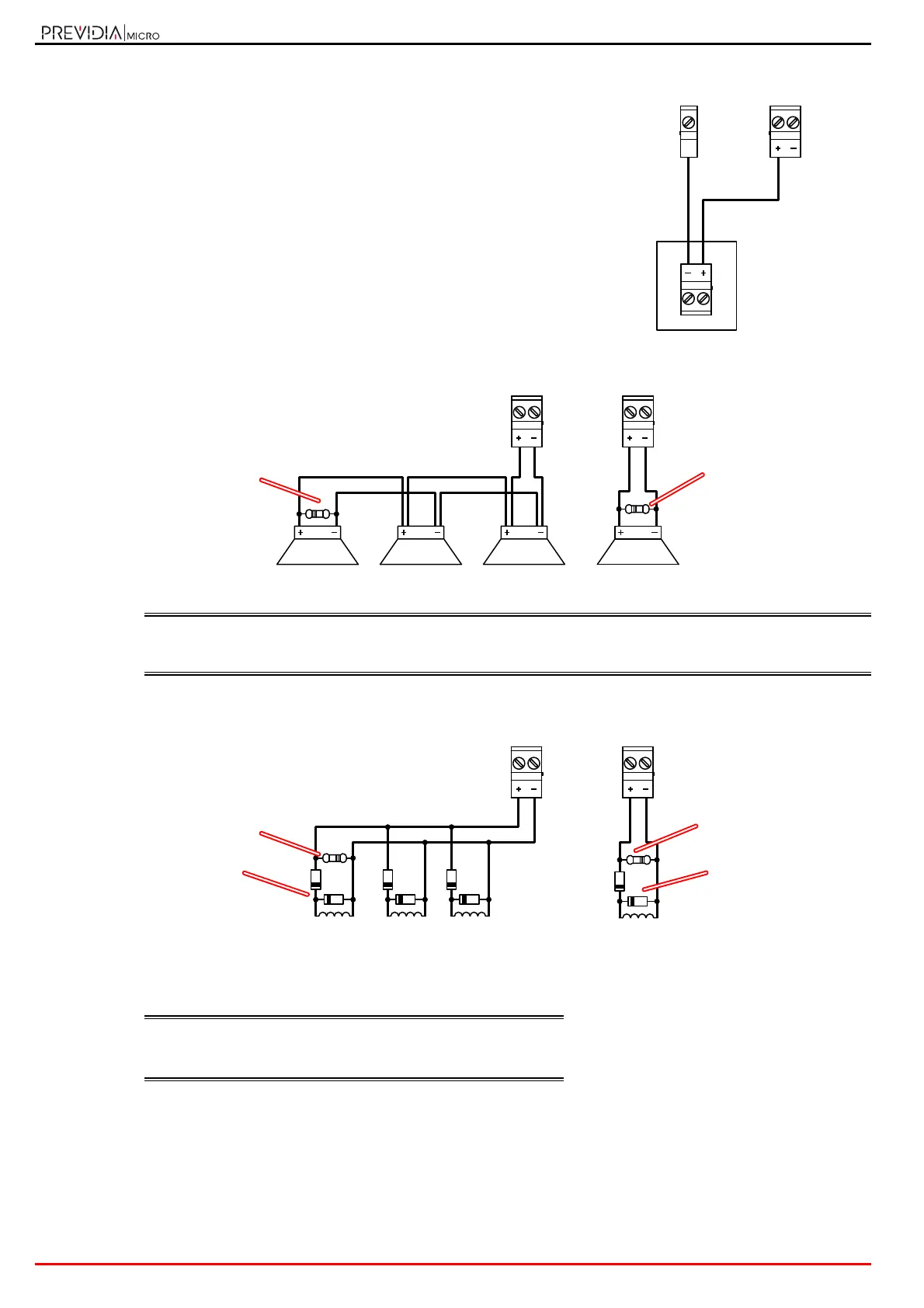
Connection of devices configured as outputs with a maximum of 100mA
Connection of polarized devices (sounders, etc.) to channels configured as outputs
The polarities refer to the active status of the output, the polarities invert for stand-by status.
EN54: If the control panel default settings are left unchanged, the I/O 1 output will result as being configured as
a type C output for the connection of audible/visual signalling devices.
The output will activate in the event of any type of fire-alarm condition.
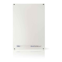
Connection of non-polarized devices (relays, etc.) to channels configured as outputs
3.6 Relay output wiring
Cables: 2/3 wire shielded cable
Proper section (minimum 0.5mm², maximum 2.5 mm²)
Compliant with local laws and regulations in force
The wiring diagram illustrates a connection to be made to one of the
Tx terminals configured as input to which is connected a generic
device with 100mA maximum output powered from a 24V source, in
the diagram the control panel AUX terminals.
1KOhm - 1W
brown, black, red
1KOhm - 1W
brown, black, red
Tx / I/Ox / AUX Tx / I/Ox / AUX
1KOhm - 1W
brown, black, red
1KOhm - 1W
brown, black, red
1N4007 diodes
1N4007 diodes
Tx / I/Ox / AUX Tx / I/Ox / AUX