18 General Description
Fire alarm and extinguishing system
2.6 PREVIDIA-M-EXP, expansion module
The optional PREVIDIA-M-EXP board allows Previdia Micro control panels to add on 8 detection lines and 6
programmable terminals.
The control panel in a small cabinet (PREVIDIA-MS) allows for installation of 2 expansion boards, whereas the control
panel in a large cabinet (PREVIDIA-ML) allows for installation of 4 expansion boards depending on the use of other
optional boards (PREVIDIA-C-DIAL or PREVIDIA-C-COM).
The zone expansion board also provides a 1A supervised output, the operating principles of which can be defined during
the system configuration phase.
The board comes with:
• Mounting plate
• 7 mounting screws
• 5 spacers
• connection cable
• EOL resistors and diodes
• Instructions manual
Technical specifications PREVIDIA-C-COM PREVIDIA-C-COM-LAN
Supply voltage 19-30 V
Consumption @ 27.6V 15mA 40mA
I
max. RS485
200mA
Operating temperature from -5°C to +40°C
SD card capacity / Maximum 32 Gbyte
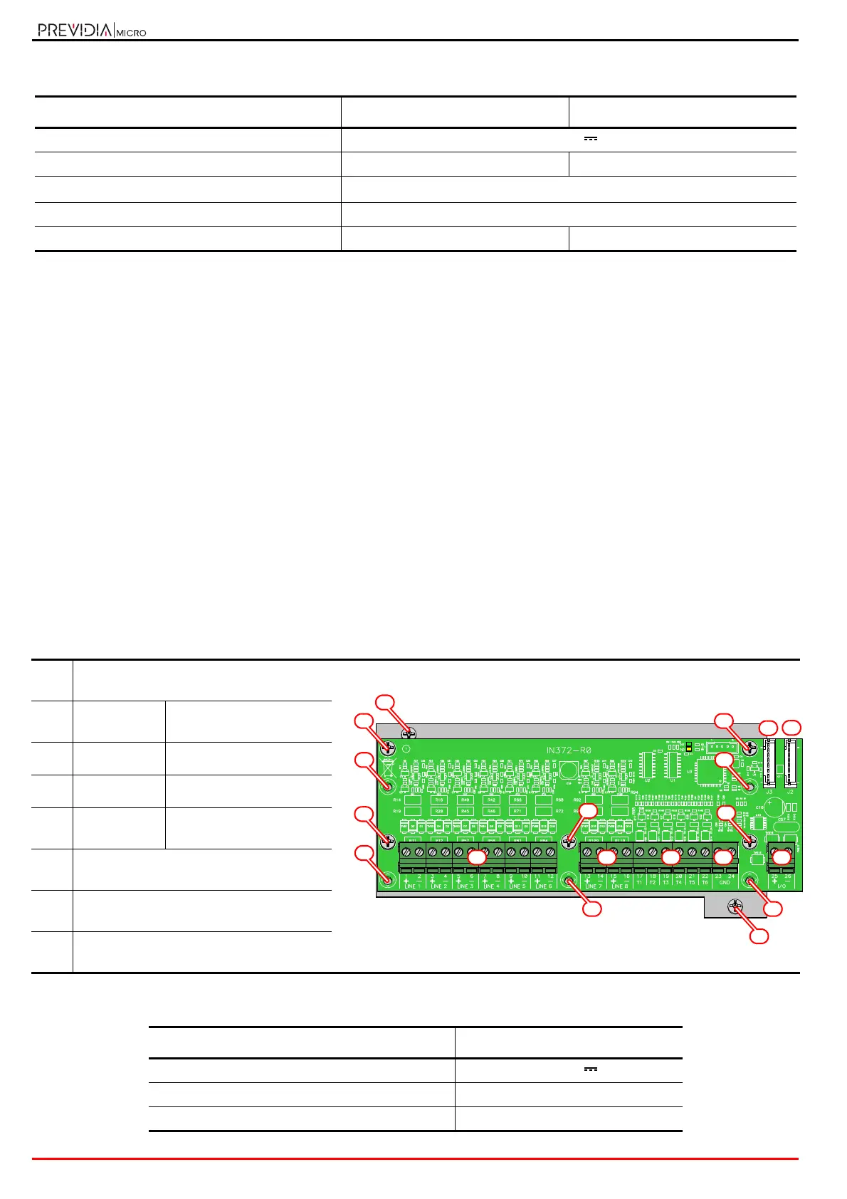
[A]
Connector for the motherboard connector
or for another PREVIDIA-M-EXP board
[B] LINE 1, ... 8
Detection line
connection terminals
[C] T 1, ... 6
Programmable terminals
[D] GND
Ground terminals
[E] I/O
Supervised output
terminals
[F]
Hole/screw for mounting the plate to the
back-box
[G]
Hole/screw for mounting the board to the
plate
[H]
Hole for the screw for mounting the
board to the one below
Technical specifications PREVIDIA-M-EXP
Power supply voltage 19-30 V
Consumption @ 27.6V 60 mA
Operating temperature from -5°C to +40°C