Inner Range Inception Security Controller Installation Manual. Rev. 6.0
© 2016 - 2023. Inner Range Pty Ltd.
6 www.innerrange.com
INTRODUCTION
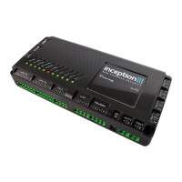
Inception is an integrated access control and intruder alarm system featuring a powerful built-in web server. No computer
software is required. System configuration and administration simply requires connecting to a network via Ethernet or Wi-Fi,
and using any web browser to navigate to Inception’s web page. See the Quickstart Guide for connection details.
Features
• USB Connection for Wi-Fi option and/or Alarm Communicator.
• Ethernet port for network connection.
• Support for local HTTPS web access. See Inception Tech Guide – HTTPS Configuration
• Tamper input for monitoring of the external enclosure.
• 8 x Universal inputs for security detectors or door monitoring.
• Support for a variety of Input EOL schemes.
• 12V DC power outputs for powering external security devices.
• LAN port for system expansion via RS-485.
• Reader port for connection of up to 8 x Inner Range SIFER Readers, SIFER-Keypad readers or 3
rd
Party OSDP Readers.
• DC power input for connection to the Inception power supply.
• Battery connection for charging of a back-up battery.
• 4 x Universal relay outputs for locks, alarm sounders, strobes or automation devices.
• Scan the QR code for quick setup of alarm monitoring via SkyTunnel.
• Comprehensive system status LED Indicators.
• ‘Send All Possible Alarms’ & ‘Commissioning Report’ features streamline configuration of monitoring station account.
• Web interface and LCD Terminal text displays can be translated into other languages.
• High-level integrations with compatible 3
rd
party alarm communicator and automation products.
• Support for Intelligent LAN Access Module including Aperio wireless doors.
NOTE: Inception Firmware. To ensure that all features, system capacities, accessory devices and compatible LAN Modules
described in this manual are fully supported, check that the Inception Controller firmware is the latest version.
System Capacities
See V1.1.0 Release notes.
Storage Units
Dependent on no. of Inputs available and no. of Inputs per unit.
Refer to ‘Inception Tech Guide – Storage Units’ for details.
8 (Via 8 OSPD<>Wiegand Conv.)
# Up to 1024 Inputs and 1024 Outputs can be programmed. For Outputs all types of hardware outputs count towards this total
including door locks, DOTL, valid & invalid (for wiegand readers), lift floor button enables, siren & strobe outputs, automation
devices, etc. (Custom outputs are not counted)
For Inputs, the limit also only applies to hardware Inputs. e.g. Zone, RF Zone, Reed, Tongue, REX, REN & ARM. Tamper Inputs
and Calculated Inputs are not counted. e.g. Door Forced, Door Held & Storage Unit Alarm. See note under ‘Report Mapping’ for
Contact ID input reporting limits.
* The Inception controller has 4 relay outputs in total. These can be used as lock relays for doors, floor button enable contacts for
lifts or general-purpose dry contact outputs.
† Inception Firmware prior to V2.0.0 only supports 32 Doors and 2000 Users.
Inception Firmware prior to V3.1.1 only supports 50,000 Events.
Inception Firmware prior to V4.0 only supports 32 Areas.
Inception Firmware prior to V5.0 only supports 512 Inputs/Outputs/Floors.
‡ 256 Wiegand readers (In & Out Readers) requires a combination of up to 127 SLAMs (i.e. 1 per door) and up to 8
OSDP<>Wiegand Converters.