26
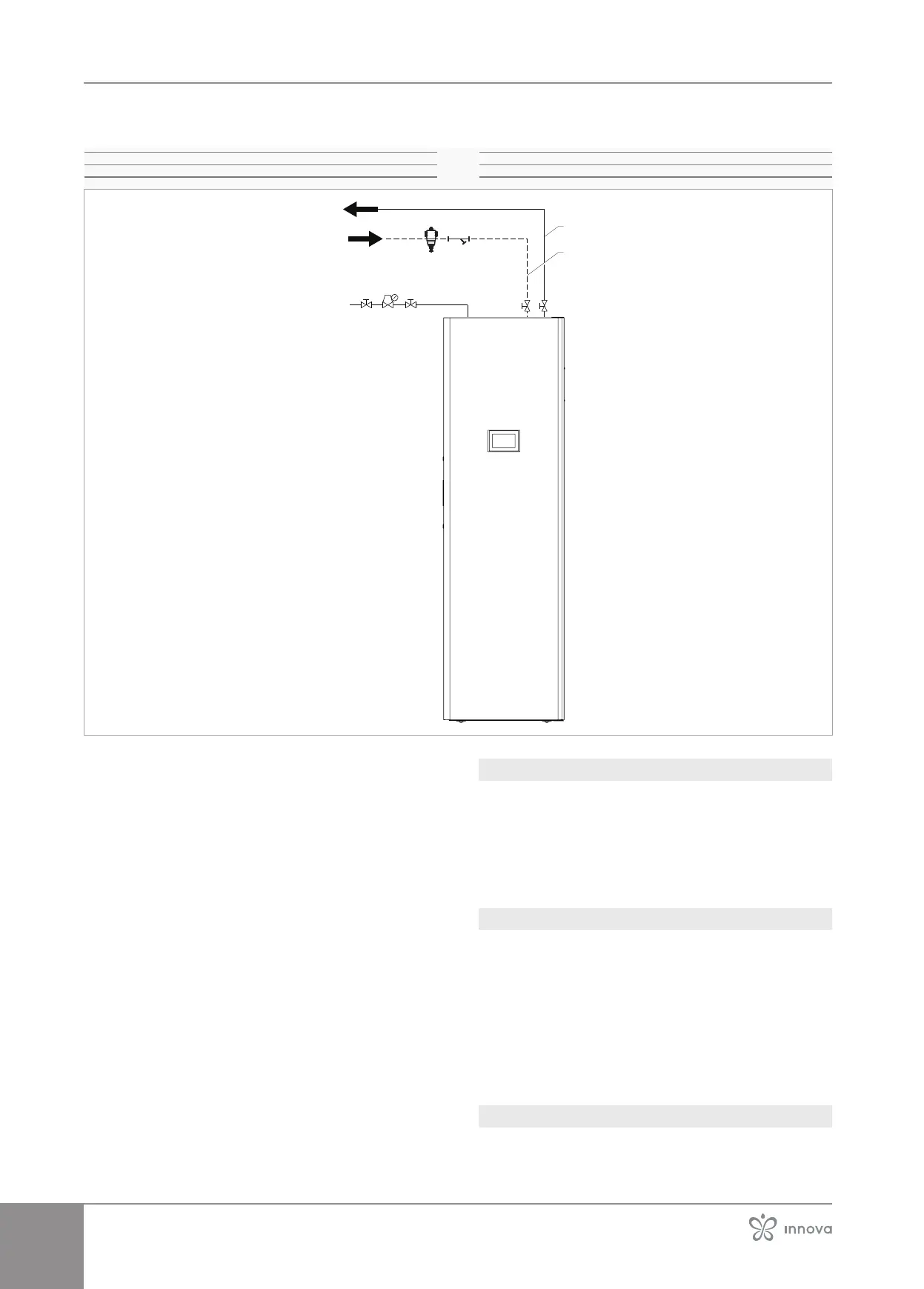
Connection diagram
1�
2� Dirt separator
3�
4�
5� Plant delivery
6� Plant return
5
6
3
2
4
1
Connection
The hydraulic connections may be made towards the wall
(concealing them from sight) or upwards. Connect a drain
pipe to water safety valve so as to prevent that some water
leakage can get inside electrical parts.
To make the connections:
– hydraulic lines positioning
– use the "wrench against wrench" method
– tighten the connections
– check for leaks
– coat the connections with insulating material
Thehydraulicconnectionsmustbecompletedbyin-
stalling:
• air release valves at the highest points of the piping
•
•
• a suitably sized storage tank for plant water
• the secondary separator kit is available as accessory
•
the appliance on the system front
The separator kit is mandatory unless it is already pres-
ent in the system.
Be careful not to invert delivery and return lines.
3�12�6 Filtration system
Itisnecessarytoinstallaltrationsystematthe
inlet of the appliance in an area accessible for
maintenance, in order to protect the appliance
from impurities in the water.
3�12�7 Safety valve
The outlet of the installed safety valve must be connected
to a suitable collection and evacuation system to prevent
any water spillage from coming into contact with the elec-
trical parts of the appliance.
The manufacturer of the appliance is not responsible
valves.
Provide a pressure reducer if the mains pressure ex-
ceeds 3 bar.
3�12�8 Coil vent
To avoid air pockets inside the circuit, place automatic
or manual venting devices at all points (higher piping, si-
phons, etc.) where air can accumulate.