22
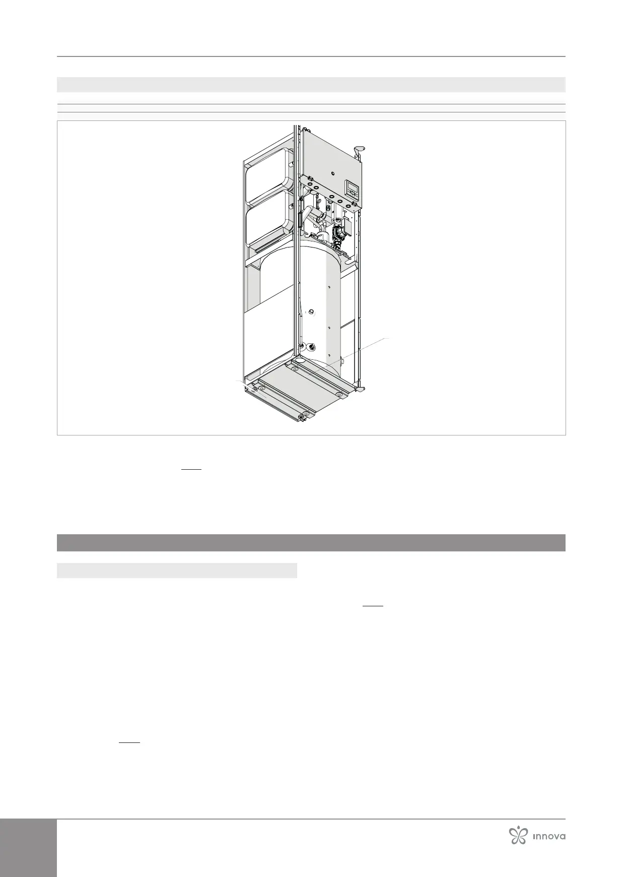
3�11�2 Positioning
1� Ball wheels for movement
2� Locking feet
2
For dimensional information, refer to chapter
"Technical information" p.64.
base to facilitate handling.
– position the appliance
– Adjust the two locking feet
Make sure that:
• it is levelled
• easy access is allowed to the hydraulic and electrical
parts
3�12 Hydraulic connections
3�12�1 Preliminary warnings
The engineer is responsible for choosing the right wa-
ter lines and their size, in accordance with good instal-
lation practices and the applicable law.
The hydraulic system is made by the installer and must
be carried out with reference to the diagrams in this
manual or on the website.
The hydraulic pipes connecting to the appliance must
the heat exchanger must always be constant.
The maximum permissible pressure drops must be
compared with the data shown in chapter "Technical in-
formation" p. 64. If higher heads are required due to
high pressure drops in the plant, an external pump with
Make sure that the quantity of water in the primary
circuit is greater than the minimum volume indicat-
rate" p.23, to prevent the risk of ice formation during
defrosting operations or continuous modulation of the
compressor frequency
It is important to note that the heat pump Control Pan-
el manages all the adjustments of the primary circuit
(plant and domestic hot water set-point, circulation
pump, dynamic set control and auxiliary heater man-
agement).
Any regulation that foresees the management of the
these regulations must be submitted to the manufac-
-
wise the warranty will be invalidated.
If the appliance is connected in parallel with a boiler,
make sure that the temperature of the water circulating
in the heat pump does not exceed 60 °C during oper-
ation.