Chapter2TechnicalSpecificationsandElectricalInstallation
12
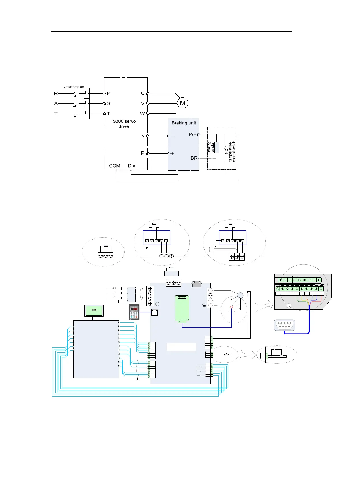
Figure 3-19 Basic wiring method 2
2.3.2 Wiring Diagram of System Application
Figure 2-3 Wiring of the IS300 system
Circuit breaker
IS300
CN2
CN2
CN3
CN5
R
S
T
M
+
–PB
U
V
W
Encoder
Servo
hydraulic pump
CGND
485B
CANH
CANL
485A
CN12
Built-in PG
card
Shield
Shield
PG connecting cable
Model: S3T113CZ-PG
PTCP
PTCN
AI1
AI2
AI3
10V
13V
GND
AO1
AO2
GND
DI1
DI2
DI3
DI4
DI5
COM
COM
OP
24V
Thermistor
T/A1
T/B1
T/C1
T/A2
T/C2
T/A3
T/C3
Oil pump enabled
DO1
DO2
DO3
DO4
DO5
COM
AO1
AO2
GND
AI1
AI2
GND
PID selection terminal 1
Slave pump address
selection terminal 1
Fault reset
CAN communication enabled
(multi-pump convergent flow)
Oil pressure reference:
0-10 V
Flow reference:
0-10 V
Current oil pressure detection:
0-10 V/0-20 mA
Current flow detection:
0-10 V/0-20 mA
COM
DI1
DI2
COM
DI3
COM
DI4
Fault output (NO/NC)
Double-discharge plunger
pump sloping switchover (NO)
Pressure control state output (NC)
CN1
CN1
Three-phase
power supply
L2
L3
L1
PE
MCCB
MC
Contactor
Magnetic core
(wind one coil)
L2
L3
L1
PE
S
T
R
Filter
U- U+ Z- Z+
COS-
B-
COS+
B-
SIN-
B-
SIN+
B-
EXC-
GND
EXC+
VCC
J4 J3 J2
Red
BlueWhite
Brown
Yellow
Green
Control cable interface
board of the servo motor
+13V
AI3
GND
Pressure sensor
+13V
AI3
GND
Pressure sensor
24Vdc
Wiring of internal
power supply
Wiring of external
power supply
Braking resistor
MDBUN
Braking unit
+
–PB
PE
BR P(+)
Braking unit
MDBUN
Braking resistor
Braking resistor
P+
PE
BR P(+)
Braking unit
MDBUN
Braking resistor
+
–PB
–
External reactor
Below 30 kW
37-55 kW Above 55 kW
1
2
3
45
6
789
J3
J3
Computer for the injection
molding machine
 Loading...

