9
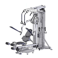
STEP 2: SWING ARM ASSEMBLY (See Step 2 Figure)
Required Hardware: STEP 2
2x (#20) Aluminum End Cap 12x (#25) Curved Washer, Chrome
14x (#26) Flat Head Socket Screw
Required Parts
(#47) Swing Arm Assembly R (#54) Swing Arm Assembly L
A.) Slide (#47) Swing Arm Assembly R over the pivot shaft of main frame,
as shown in STEP 2. NOTE: Lift spacer in between bearings to allow insertion.
B.) Secure using:
1x (#20) Aluminum End Cap 1x (#26) Flat Head Socket Screw
As seen in Step 2 Figure
C.) Place the (#47) Swing Arm Assembly R on top of the styrofoam support block with the red
dot, so the swing arm doesn’t touch the floor.
D.) Slide the (#13) Pedal Arm that is already attached to unit, into the (#47) Swing Arm
Assembly R
E.) Secure using:
6x (#25) Curved Spacers, Chrome 6x (#26) Flat Head Socket Screw
As seen in Step 2 Figure
F.) Slide (#54) Swing Arm Assembly L over the pivot shaft of main frame,
as shown in Step 2. NOTE: Lift spacer in between bearings to allow insertion.
G.) Secure using:
1x (#20) Aluminum End Cap 1x (#26) Flat Head Socket Screw
As seen in Step 2 Figure
H.) Place the (#54) Swing Arm Assembly L on top of the styro foam support block with the
red dot, so the swing arm doesn’t touch the floor.
I.) Slide the (#13) Pedal Arm that is already attached to unit, into the (#54) Swing Arm
Assembly L
J.) Secure using:
6x (#25) Curved Spacers, Chrome 6x (#26) Flat Head Socket Screw