47
System interconnections
Product Support: www.instron.com
System interconnections
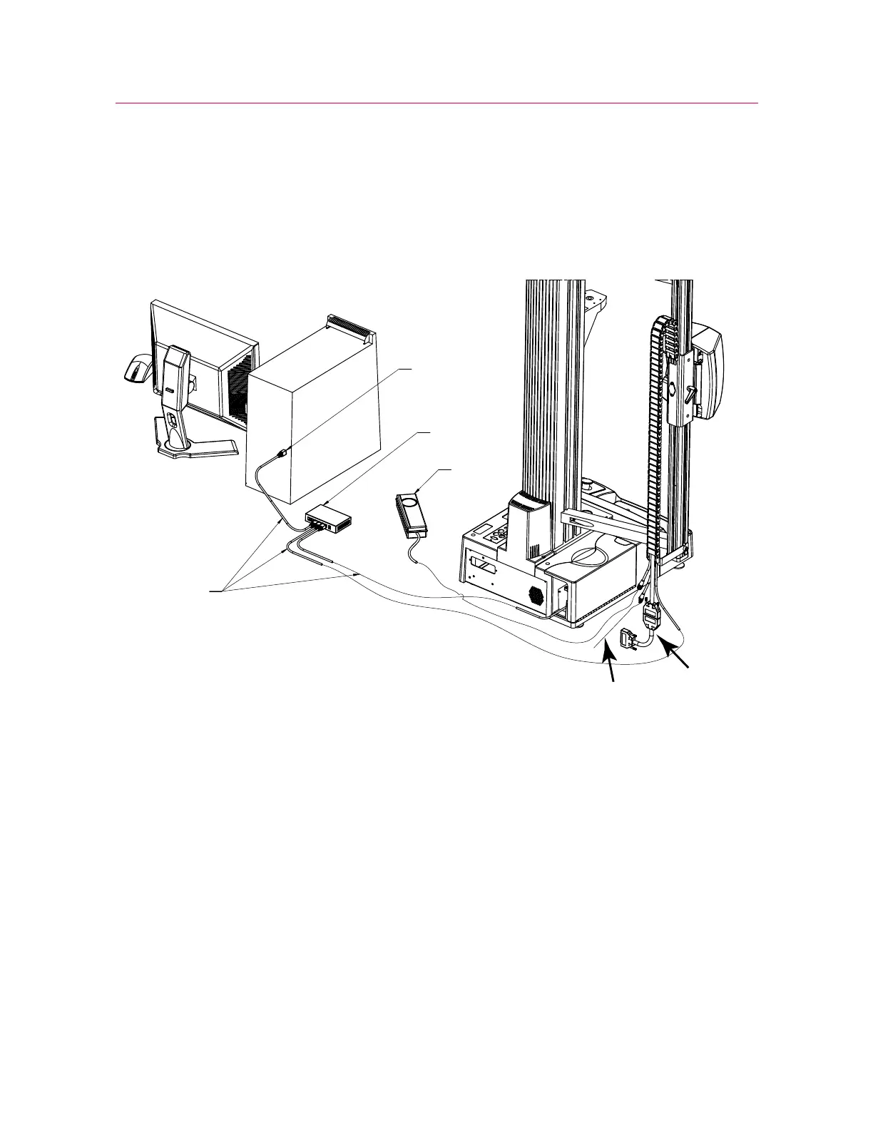
Figure 22 on page 47 shows an overview of the interconnections between the video
extensometer, the controller on the load frame and the computer running the control
software.
Figure 22. Video extensometer system interconnections (5900 shown)
The numbers in the following description refer to Figure 22 on page 47.
The video extensometer connects to power (1), the Ethernet switch (2) and the
appropriate strain connector on the frame controller via the interface cable and an
adapter cable (3). The Ethernet switch (2) connects to the computer’s Ethernet
connection (4) and to the frame controller’s Ethernet connection. There are three
Ethernet cables (5). An additional cable (6) is the sync cable required for use with DIC
Replay software. If you are using DIC Replay, connect this cable to the
SYNC connector
on the controller panel on the load frame.
Figure 23 on page 49 shows a closer view of the video extensometer connections. The
power cable (1) and the Ethernet cable (2) are shown with the video extensometer
interface cable and the video extensometer adapter cable (3). The adapter cable shown