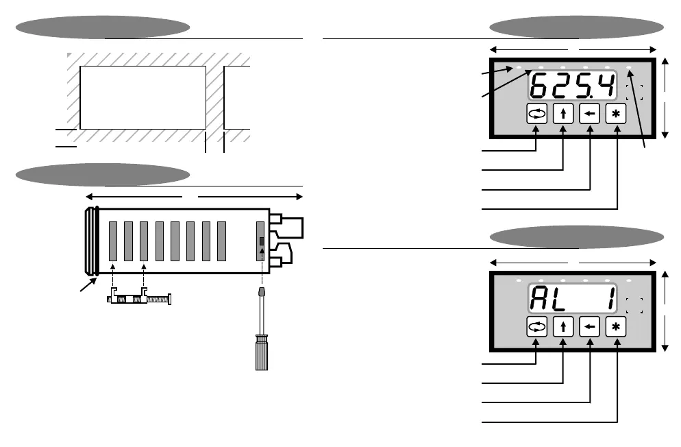
Fastening
The supplied fastening
clips may be fitted on
the side or the top /
bottom of the housing.
Ensure that the clip &
screw is mounted as
shown here.
Caution : Do not
overtighen the screws.
Min
12
45
92
Installation
To gain access to the
circuit boards, switch
power off and remove
terminals from the
back of the housing.
Observe safety
precautions. Use a
screwdriver to clip the
back-plate off.
During programming mode
Display & Keypad
147
Panel Cutout
Installation
48
96
Enter
Programming menu
Move to next digit
Increment digit / change selection
Total
LED
(display
shows
totalised
value)
48
96
2341
Reset peak value (option 3012 only) /
Auto-zero (option 3014 only)
Print on demand (comms option only)
Show normal value (option 3012 only)
Show peak / valley hold value
(option 3012 only)
2341
kPa
All dimensions in mm
During normal display mode
Display & Keypad
Page 5
Min
12
DIN 1/8 cutout
O-ring sealing
gasket supplied
as standard
Rate LED
(display shows rate)
Alarm LEDs
(illuminated whenever
relays are energised)