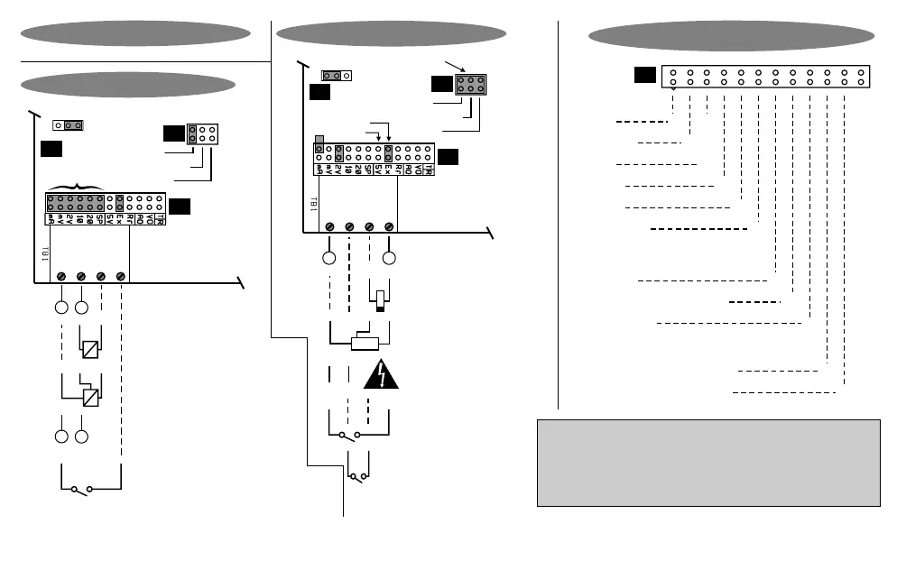
Hardware Link Selection For J5
mA XX
X
200 mV
2 V
10 V
20 V
Special*
X
X
X
X
X
Analog Output
+5VDC X
+24VDC, current limited X
+2.5V Vref X
X
Terminal 3 Voltage Output
0 - 20 / 4 - 20mA (option)
0 - 10V (option)
X
Input
J5
S
+
-
+
-
L
N
Namur
Circuit board
Frequency:
Display Hold (Option 3026)
Potential free contact
Namur
PNP / Volts
J8
P
C
Counts /
Process
input
selector
1. In Lo
3. + Vout
4. Dig In
2. In Hi
J7
J5
NPN
Select sensor type
Connections & Links
Excitation select:
NPN / PNP
Generated frequency
(24V maximum)
2-wire NAMUR sensor
(must work with
5V excitation)
Line / mains frequency
measurement option
(Option 3021)
3-wire proximity switch /
encoder (NPN or PNP type)
Counter : Reset
Circuit board
True RMS AC (Option 3005)
Ohm / Tap input (Option 3011)
Process inputs of type
200mV, 2V, 10V, 20V,
0/4-20mA. (Select J5 link !)
+
-
Namur
PNP / Volts
J8
P
C
Counts /
Process
input
selector
1. In Lo
3. + Vout
4. Dig In
2. In Hi
J7
J5
Digital
sensor
selection
NPN
S
+
-
Select input link
(see J5 link table)
Process Inputs
4 - 20 mA, 2-wire
transmitter
0 - 20 mA, 3-wire
transmitter
Freq / Count Inputs
-
+
Totaliser reset OR
Rate vs Total select OR
Reset peak / valley hold (Option 3012) OR
Remote auto-zero (Option 3014) OR
Display hold (Option 3026)
Note : Counter or totaliser reset may also be achieved by pressing the 'Enter' key (press for 3 seconds). External reset is almost instantaneous.
Note : The "special" (SP) input is normally configured for potentiometer input. It can however be configured to order as per customer's requirements.
Note : For 2- wire NAMUR sensors, the proximity switch must be able to operate from 5V supply.
Place hardware links as shown in the diagrams.
Remember : Configuring this instrument requires two steps. (1)
Select the correct hardware links as shown. (2) Program the
instrument with the programming chart on page 8 & 9.
Page 6