EasyManua.ls Logo

INSTROTECH 4001 - User Manual

INSTROTECH 4001
20 pages
Print Icon
To Next Page IconTo Next Page
Loading...
Universal Process /
Counter / Frequency /
Integrator / Totaliser
Indicator
Operating Manual for Models :
4001 / 4011 / 5001 / 5011 / 5600 /
8001 / 5001-T / 8001-T
Question and Answer IconNeed help?

Do you have a question about the INSTROTECH 4001 and is the answer not in the manual?

Summary

Safety and Cleaning

General Safety Precautions

Essential safety guidelines for handling the equipment, including shock prevention and proper procedures.

Cleaning Instructions

Guidelines for cleaning the instrument, emphasizing safe methods and materials to avoid damage.

Introduction to Models

Model Overview

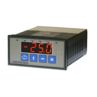
Introduces universal process indicators and details specific model features and capabilities.

Electrical Specifications

Details key electrical parameters such as accuracy, resolution, temperature coefficient, and operating ranges.

Input Ranges and Sensor Excitation

Lists available input signal ranges and specifies sensor excitation voltage options for various sensors.

Power and Specifications

Power Supply Options

Describes standard and optional power supply configurations for the instrument.

Programmable Specifications

Outlines programmable features for 4-digit and 5½/6/8-digit models, including scaling and units.

Other Specifications

Covers physical aspects like housing dimensions, materials, and front panel protection rating.

Installation and Display

Panel Cutout Requirements

Provides dimensions and specifications for creating a panel cutout for instrument installation.

Mounting and Fastening

Details the methods for securely fastening the instrument into the panel using supplied clips.

Display and Keypad Interface

Illustrates the front panel layout for both normal operation and programming modes.

Connections and Wiring

Process Input Connections

Diagrams and guidance for connecting various process input signals to the instrument.

Frequency;Count Input Wiring

Specific wiring instructions for frequency and count input signals.

Hardware Link Configuration

Explains how to set hardware links for different input and output configurations.

Advanced Connections

Potentiometer Input Setup

Details the connection and link configuration for potentiometer inputs.

Option Connection Details

Shows wiring for optional features like analog output, RS232/RS485, and alarms.

Power Supply Link Settings

Illustrates how to configure power supply links for different voltage inputs.

Programming Guide

Programming Chart Overview

A flowchart illustrating the instrument's programming sequence and menu structure.

Programming Notes and Tips

Important notes and advice for users navigating the programming menus and options.

Input Configuration Menus

Input Type Selection Menus

Details the various input configuration menus like 'InP', 'Pro', 'FrE9', 'P.Int'.

Incr Feature and Linearisation

Explains the 'Incr' feature for display increment and linearisation options.

Display Code Reference

Display Codes Explained

A comprehensive guide to understanding the various display codes shown during operation and programming.

Programming Example

Setting Up Alarm Values

A step-by-step example demonstrating how to configure alarm setpoints.

Communications Protocol

Asciibus Protocol Details

Explains the ASCIIbus communication protocol for options 3002 and 3013.

Model 5001-T Calculations

I.FS.H Value Calculation Example 1

Demonstrates how to calculate the Integrated Full Scale Hour value with a specific example.

Model 5001-T Calculations

I.FS.H Value Calculation Example 2

Provides a second example for calculating the Integrated Full Scale Hour value.

Product Options

Option 3000: Lineariser

Describes the lineariser option for non-linear signal correction.

Option 3001-P: Two Set Point (Solid-State)

Details the two set point option using solid-state relays for alarms.

Option 3001-M: Two Set Point (Electro-Mechanical)

Details the two set point option using electro-mechanical relays for alarms.

Option 3002: RS485 Serial Interface

Explains the RS485 serial communication interface option.

Option 3003: Analogue Output

Describes the option for providing analogue voltage or current output signals.

Option 3004-P: One Set Point (Solid-State)

Details the one set point option using solid-state relays.

Option 3004-M: One Set Point (Electro-Mechanical)

Details the one set point option using electro-mechanical relays.

Product Options

Option 3006: Isolated Options

Provides 1500V isolation for output and communication options.

Option 3008: Galvanic Isolation Supply

Offers an isolated 8-30VDC power supply and load cell excitation.

Option 3009: Parallel BCD Output

Enables parallel BCD output as an additional slot card.

Option 3010: Wide Range Power Supply

Allows operation from a wide range of AC/DC power supplies.

Option 3011: Ohms; Tap Input

Measures resistance and tap positions on transformers.

Option 3012: Peak;Valley Hold

Displays and holds the maximum or minimum input signal value.

Option 3013: RS232 Serial Interface

Explains the RS232 serial communication interface option.

Product Options

Option 3014: Auto-zero Option

Allows the operator to zero the display at any time during measurement.

Option 3017-P: Three Set Points (Solid-State)

Provides three alarm set points using solid-state relays.

Option 3017-M: Three Set Points (Electro-Mechanical)

Provides three alarm set points using electro-mechanical relays.

Option 3018-P: Four Set Points (Solid-State)

Details the four set point option using solid-state relays.

Option 3018-M: Four Set Points (Electro-Mechanical)

Details the four set point option using electro-mechanical relays.

Product Options

Option 3021: Frequency Measurement

Measures line/mains frequency accurately (0.00 to 99.99 Hz).

Option 3022: Vertical Bar Graph Display

Provides a graphic linear representation of the measured process variable.

Option 3023: Pulse Output Option

Generates pulses based on totalising display changes for selected meters.

Option 3024: Manual Set Point Station

Simulates an input value without physical analog input.

Product Options

Option 3024: Manual Set Point Station (Application)

Explains how to change values and application of the manual set point station.

Option 3025: Keypad Lock Option

Prevents unauthorized access to the programming menu with different lockout levels.

Option 3026: Display Hold Option

Allows freezing the display via an external potential-free contact.

Option 3028: Galvanic Non-Isolation Supply

Provides a non-isolated 8-30VDC galvanic power supply.

Diagrams and Declarations

Diagram P Wiring

Wiring diagram for options using Diagram "P" for connections.

Diagram M Wiring

Wiring diagram for options using Diagram "M" for connections.

Declaration of Conformity

States compliance with EC directives for universal process indicators.

Guarantee Information

Product Guarantee Terms

Details the warranty period, terms, and manufacturer's responsibilities.

Overview

This document describes the operating manual for a series of universal LED process indicators, including Models 4001, 4011, 5001, 5011, 5600, 8001, 5001-T, and 8001-T. These instruments are designed for accurate measurement and display of various process variables with both analog and digital inputs, such as pressure, level, flow, frequency, up and down counting, DC voltages or currents, and revolutions per minute. Selected models also offer integration and totalization of the input signal.

Function Description

The indicators are versatile and can be applied to a wide range of industrial processes.

  • Model 4001 is a 4-digit indicator (-1999 to 9999) that supports process inputs of type mA, mV, V, potentiometer, and frequency.
  • Model 5001 is a 5½-digit indicator (-199999 to 199999) that includes all features of Model 4001, plus process x frequency functions, count rate, and totalizer capabilities.
  • Model 5600 is a 6-digit indicator (-199999 to 999999) with all features of Model 5001, though set points and other options are limited to 5½ digits.
  • Model 5001-T is a 5½-digit indicator (-199999 to 199999) that offers all features of Model 5001, with the addition of process integration and totalization.
  • Model 8001 is a 5½-digit rate display indicator with an 8-digit count display.
  • Model 8001-T includes process integration and totalization in addition to the features of Model 8001.
  • Models 4011 & 5011 provide Asciibus serial input for remote display of serial information.

The built-in sensor excitation supply is link-selectable for 2-wire/3-wire transmitters, encoders, and potentiometer input.

Important Technical Specifications

Electrical Specifications:

  • Accuracy & Linearity: 0.05% of Full Scale (F.S.) or 1 count (0.5% of F.S. or 1 count for Option 3011/15/27).
  • Internal Resolution: 20000 counts (bi-polar).
  • Temperature Coefficient: 20 ppm/°C typical.
  • Settling Time: 0.5 seconds for process inputs; 5 milliseconds for frequency input (no filter).
  • Operating Temperature Range: -10 to +50°C.
  • Storage Temperature Range: -40 to +80°C.
  • Humidity: < 85% non-condensing.
  • Warm-up Time: None required.
  • Electro-mechanical Relays: 250V AC, 30V DC, 2A, PF=1.
  • Solid State Relays: 400V AC/DC, 0.5A, PF=1.
  • Analogue Output Accuracy: 0.1% of full scale, 12 bits.
  • Current Analogue Output Load: 500 Ω maximum.
  • Voltage Analogue Output Load: 1 kΩ minimum.
  • Memory Retention: Full non-volatile operation.
  • Option 3006 Isolation Rating: 1500 V.

Input Ranges:

  • 0-20 mA, 4-20 mA.
  • 0-200 mV, 0-2 V, 0-10 V, 0-20 V.
  • Special (potentiometer input).
  • 0.2 Hz - 40 kHz (24V max, up to 0.01 Hz resolution).

Sensor Excitation:

  • 24V DC: (17-26V), current limited. For 2-wire transmitters, proximity switches, or encoders. With Option 3010, current capability increases to 100mA.
  • 5V DC: ± 1%, maximum 25mA.
  • 2.5V DC: Precision reference, 2mA max for potentiometer (2 kΩ min).

Power Supply:

  • Standard: 115 / 230 VAC ± 10%, link selectable, 50/60Hz, 5VA typical.
  • Optional:
    • 8-30VDC isolated power supply (Option 3008), 5VA typical.
    • 8-30VDC non-isolated, 5VA typical.
    • 95V-265V AC/DC isolated power supply (Option 3010), 5VA typical.

Other Specifications:

  • Housing: DIN 48 x 96, 147mm depth, industrial strength single piece, flame retardant ABS plastic (UL94 V-0).
  • Circuit Board: Flame retardant material (UL94 V-0).
  • Front Facia Rating: IP65 (with O-ring seal supplied as standard).

Programmable Specifications (4 Digit Models):

  • Zero & Full Scale Setting: -1999 to 9999.
  • Decimal Point: Adjustable on all digits.
  • Freq / Counter Scaler: 00.01 to 99.99.
  • Frequency Units: Selectable Hz or RPM.
  • Frequency Filtering: None, 0.5, 1.1, or 4.5 seconds.
  • Counter Features: Reset (count up) / Preset (count down).
  • Analog Output Zero & Span: -1999 to 9999.
  • Alarm Setpoint Values: -1999 to 9999.
  • Alarm Hysteresis: 0 to 255 (default 1).
  • Alarm Delay: 0 to 255 seconds (default 0).
  • Alarm Relay Settings: Selectable HIGH or LOW alarm.
  • Alarm Relay State: Selectable NO or NC.
  • Unit Address: 0 to 99.
  • Baud Rate: 2400, 4800, 9600, 19200.

Programmable Specifications (5½ / 6 / 8 Digit Models):

  • Zero & Full Scale Setting: -199999 to 199999.
  • Decimal Point: Adjustable on all digits.
  • Process Filtering: 0.0 to 10.0 seconds.
  • Freq / Counter Scaler: 0.05 to 1999.99.
  • Frequency Units: Selectable Hz or RPM.
  • Frequency Filtering: None, 0.5, 1.1, or 4.5 seconds.
  • Counter Features: Reset (count up) / Preset (count down), Counter rate & totalizer.
  • Analog Output Zero & Span: -199999 to 199999.
  • Alarm Setpoint Values: -199999 to 199999.
  • Alarm Hysteresis: 0 to 255 (default 1).
  • Alarm Delay: 0 to 255 seconds (default 0).
  • Alarm Relay Settings: Selectable HIGH or LOW alarm.
  • Alarm Relay State: Selectable NO or NC.
  • Unit Address: 0 to 99.
  • Baud Rate: 2400, 4800, 9600, 19200.

Usage Features

Installation:

  • The device fits a DIN 1/8 cutout (92x45mm).
  • Fastening clips can be fitted on the side, top, or bottom of the housing. An O-ring sealing gasket is supplied for IP65 front facia rating.
  • Access to circuit boards requires switching off power, removing terminals, and clipping off the back-plate with a screwdriver.

Display & Keypad (Normal Display Mode):

  • Rate LED: Illuminates when the display shows rate.
  • Alarm LEDs: Illuminate when relays are energized.
  • Total LED: Illuminates when the display shows totalized value.
  • Buttons:
    • Menu (circle arrow): Print on demand (comms option only).
    • Up arrow: Show peak/valley hold value (Option 3012 only).
    • Left arrow: Show normal value (Option 3012 only).
    • Star: Reset peak value (Option 3012 only) / Auto-zero (Option 3014 only).

Display & Keypad (Programming Mode):

  • Menu (circle arrow): Programming menu.
  • Up arrow: Increment digit / change selection.
  • Left arrow: Move to next digit.
  • Star: Enter.

Programming:

  • To enter programming mode, press the menu key for a few seconds. If no key is pressed for 20 seconds, the instrument returns to normal display mode.
  • Configuration involves two steps: (1) selecting correct hardware links (refer to diagrams on pages 6 & 7) and (2) programming the instrument using the programming chart.
  • The programming chart provides a simplified flowchart for experienced users. A programming example is included for new users.
  • Options not ordered will not appear in the programming sequence.

Input Configuration:

  • Hardware links on J5 are used to select input types (mA, mV, V, Special) and terminal 3 voltage output (+5VDC, +24VDC current limited, +2.5V Vref).
  • Hardware links on J7 and J8 select sensor type (NPN/PNP, Namur) and process/count input.
  • Potentiometer input requires specific link configurations.

Options:

  • Option 3000 (Lineariser): For square root, cylinder, or sphere applications. Can be toggled ON/OFF in the 'PRo' menu.
  • Option 3001-P/M (Two Set Point): Provides two alarm set points with solid-state (P) or electro-mechanical (M) relays.
  • Option 3002 (RS485 Serial Interface): Selectable DIGIbus or ASCIIbus protocol.
  • Option 3003 (Analogue Output): 0-20mA / 4-20mA / 0-10V output.
  • Option 3004-P/M (One Set Point): Similar to 3001-P/M but with a single alarm.
  • Option 3006 (Isolated Options): Provides 1500V isolation for analogue output, RS232, or RS485.
  • Option 3008 (Galvanic Isolation 8-30V Supply): Provides an 8-30VDC galvanically isolated power supply and excitation for up to four load cells.
  • Option 3009 (Parallel BCD Output): Additional slot-in card.
  • Option 3010 (95V-265V AC/DC Power Supply): Allows operation from a wide range of AC & DC supplies.
  • Option 3011 (Ohms / Tap Input): Measures resistance and tap positions on transformers.
  • Option 3012 (Peak Or Valley Hold): Displays and holds max or min input signal value. Activated in 'Opt' menu. Peak/valley values can be shown with up/side arrows and reset with the star key or external contact. Not compatible with Option 3014.
  • Option 3013 (RS232 Serial Interface): For PC connection.
  • Option 3014 (Auto-zero): Allows operator to zero display at any time. Activated ON/OFF in 'Opt' menu. Zeroing via star key or external contact. Not compatible with Option 3012 or 'd.tot'/'p.int' input menu selections.
  • Option 3017-P/M (Three Set Points): Provides three alarm set points with solid-state (P) or electro-mechanical (M) relays.
  • Option 3018-P/M (Four Set Points): Similar to 3017-P/M but with four relays.
  • Option 3021 (Line / Mains Frequency Measurement): Measures power supply frequency (0.00 to 99.99 Hz).
  • Option 3022 (Vertical Bar Graph Display): Graphic linear representation of process variable. Instrument must be mounted vertically.
  • Option 3023 (Pulse Output): Relay of alarm #1 pulses when totalizing display changes by one count. Max pulse rate is two pulses per second.
  • Option 3024 (Manual Set Point Station): Simulates an input value, edited with front keys. Analog output follows display if ordered.
  • Option 3025 (Keypad Lock): Prevents unauthorized access to programming menu. Three levels of lockout: Level 0 (none), Level 1 (alarm values only), Level 2 (total lockout).
  • Option 3026 (Display Hold): Freezes display via external potential-free contact. Not available for 5001-T & 8001-T.
  • Option 3028 (Galvanic non Isolation 8-30V Supply): 8-30VDC non-isolated galvanic power supply.

Maintenance Features

Safety:

  • Always switch off and isolate the instrument from mains power before removing the circuit board.
  • Do not apply power to the circuit board when removed from its housing unless specifically instructed.
  • Use insulated tools and test equipment when working on live equipment, and do not work alone.
  • When fitting option boards, ensure circuit boards are securely fastened back in the housing before powering up.
  • Observe full anti-static precautions when handling circuit boards.
  • Replace external mains fuse with one of an equivalent type.

Cleaning:

  • Do not clean the instrument while it is on.
  • Avoid harsh abrasives, solvents, scouring cleaners, and alkaline cleaning solutions (e.g., washing soda), especially on the display window.
  • Wipe the outside of the instrument with a slightly damp clean cloth (moistened with water only).
  • Do not attempt to wipe the inside of the instrument.

Guarantee:

  • The product is guaranteed against faulty workmanship or defective material for a period of two years from the date of delivery.
  • The manufacturer will replace defective equipment returned (transportation costs prepaid) within the guarantee period, provided there is no evidence of abuse or mishandling.
  • The manufacturer reserves the right to alter any specification without notice.

INSTROTECH 4001 Specifications

General IconGeneral
BrandINSTROTECH
Model4001
CategoryIndustrial Equipment
LanguageEnglish