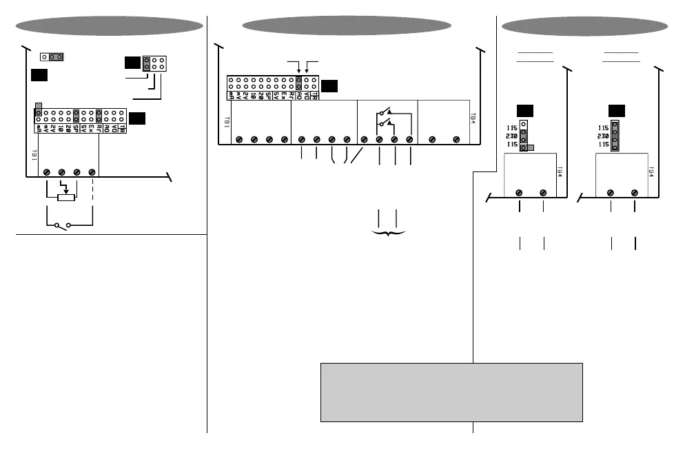
For 230V
operation
For 115V
operation
DC supply
AC supply
-
+
NL
J2
Neut (+)
Power
supply
selector
Live (-)
*** External 0.5A fuse recommended ***
AC supply
-
+
NL
J2
Neut (+)
Power
supply
selector
Live (-)
DC supply
Power Supply Links
S
+
-
Circuit board
Display hold (Option 3026)
Potentiometer input
(Link as shown)
Namur
PNP / Volts
J8
P
C
Counts /
Process
input
selector
1. In Lo
3. + Vout
4. Dig In
2. In Hi
J7
J5
Digital
sensor
selection
NPN
Link as shown
Analogue
output
option
(see links
on J5)
RS232/
RS485
option
Alarm 1
Alarm 2
Alarm com
-
+
1. In Lo
3. + Vout
4. Dig In
7. +D (Rx)
5. -An out
2. In Hi
8. -D (Tx)
9. DGND
10
6. +An out
Neut (+)
11
12
Live (-)
Circuit board
J5
Link here for
voltage output
Alarm connections
for 3001/4-P only.
Solid state relays,
400V AC/DC,
0.5 A max, PF=1
Interposing relays
recommended for
heavy duty applications
Pulse output
(Option 3023)
Option Connections & Links
Linked for
current output
Page 7
J2 link positions do not matter for DC supply
or for Option 3008 or Option 3010.
Place hardware links as shown in the diagrams.
Remember : Configuring this instrument requires two steps. (1)
Select the correct hardware links as shown. (2) Program the
Potentiometer Input