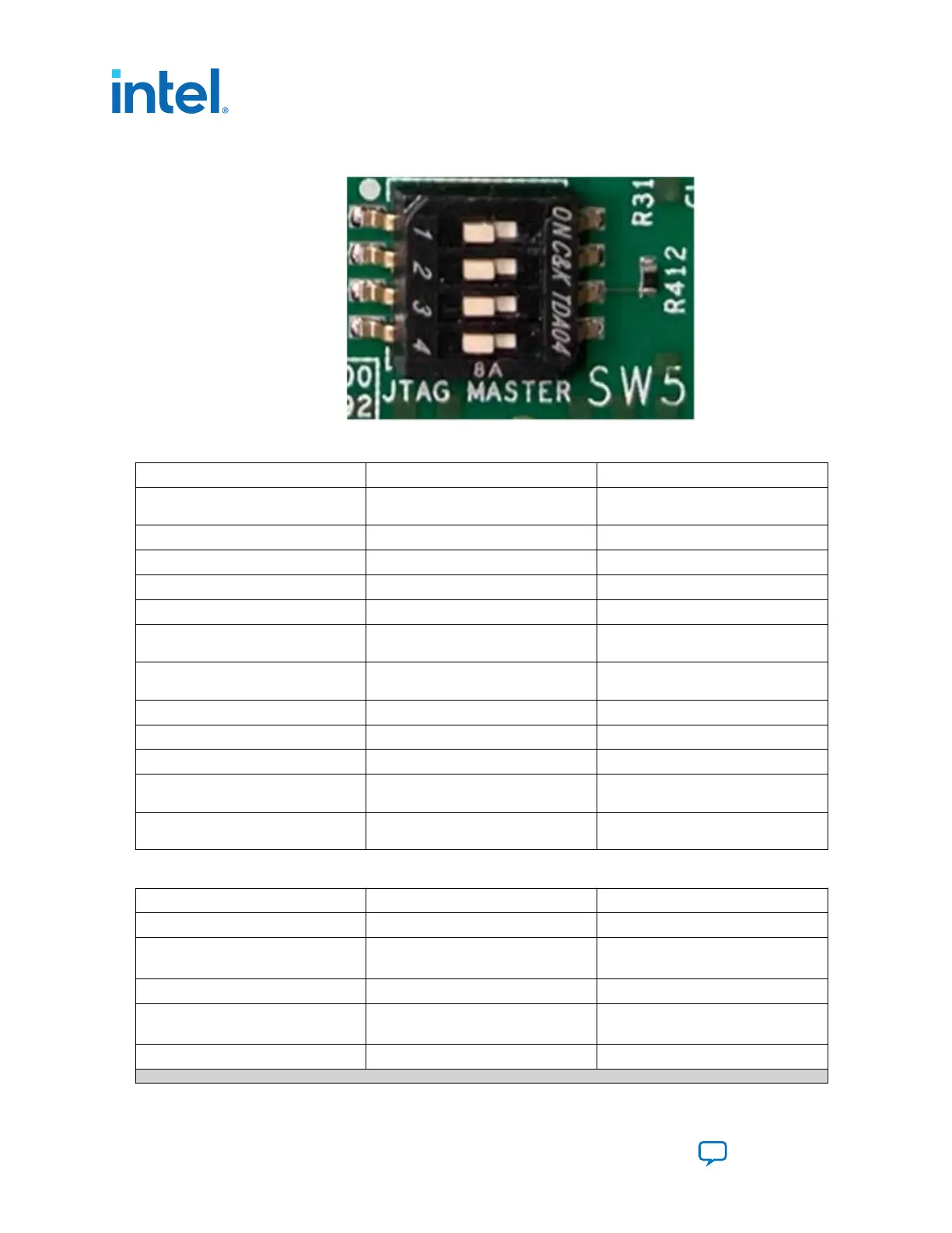
Figure 7. SW5[1:4] Switch Setting
Table 5. Connectors on the Development Kit
Board Reference Type Description
J11 Auxiliary power connector For the external 12V auxiliary power
supply or power adapter
J12 I2C/PMBus connector For accessing core power controller
J13 I2C connector For accessing to the main I2C1 bus
J3 QSFPDD_0 connector —
J4 QSFPDD_1 connector —
J8 USB connector For programming the FPGA using on-
board Intel FPGA Download Cable II
J10 External JTAG header For use with the external download
cable
J1 DIMM A connector DDR4/DDRT Dual DIMM A
J2 DIMM B connector DDR4/DDRT Dual DIMM B
J5 PCIe x16 Gold Finger —
J6, J7 CXL/PCIe connectors For connecting the external CXL/PCIe
MCIO cables
J24 Fan connector For connecting to the heatsink cooling
fan
Table 6. LEDs on the Development Kit
Board Reference Type Description
D1 QSFPDD_0 Link/Activity LED Green LED - User defined
D2 QSFPDD_0 Link/Activity LED (Dual
color)
Yellow LED – User defined
Green LED - User defined
D3 QSFPDD_1 Link/Activity LED Green LED - User defined
D4 QSFPDD_1 Link/Activity LED (Dual
color)
Yellow LED – User defined
Green LED - User defined
D5 USER LED 0 Green LED for USER LED 0
continued...
3. Development Board Setup
683288 | 2022.09.22
Intel
®
Agilex
™
I-Series FPGA Development Kit User Guide
Send Feedback
14

 Loading...


