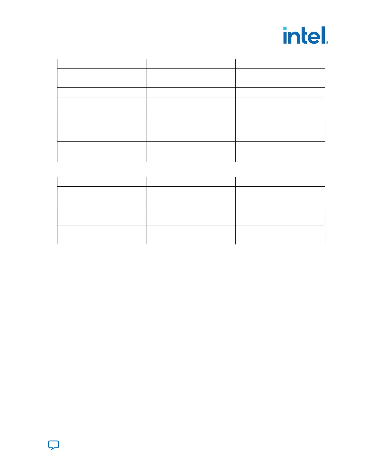
Board Reference Type Description
D7 USER LED 1 Green LED for USER LED 1
D8 USER LED 2 Green LED for USER LED 2
D10 USER LED 3 Green LED for USER LED 3
D6 POWER GOOD LED Blue LED:
• ON: All powers are good.
• OFF: Power failure
D11 CONFIG DONE LED Green LED:
• ON: FPGA configuration successful
• OFF: FPGA configuration failed
D9 Over Temp LED Red LED:
• ON: FPGA over temperature
condition
Table 7. Push-Buttons on the Development Kit
Board Reference Type Description
S1 CPU Reset Push to reset FPGA
S2 PCIe Reset Push to reset PCIe bus on MCIO
connectors (J6 and J7)
S3 CXL Reset Push to reset CXL bus on MCIO
connectors (J6 and J7)
S4 USB PHY Reset Push to reset on-board USB PHY
S5 QSFPDD_1 Reset Push to reset F-tile for QSFPDD_1 port
3.2.2. Perform Board Restore through Intel Quartus Prime Programmer
The development kit ships with FPGA design examples stored in the QSPI flash device
and system Intel MAX 10 pre-programmed. If you want to restore board QSPI flash
with factory default image, follow these steps:
1. Connect the USB cable between J8 USB connector and your computer.
2. Open Intel Quartus Prime Programmer GUI, detect the JTAG chain, attach the
factory default image on system Intel MAX 10 device.
3. Select programming options and click the program button.
3.3. How to Generate a POF Image to Program the Flash
Note:
If you already have the Programmer Object File (.pof), you can skip this section.
To generate a POF image to program the flash on the development kit, follow these
steps:
1. Open the Intel Quartus Prime Pro Edition software and click on File >
Programming File Generator to launch the Programming File Generator too.
2. In the Device family list, select Agilex, and in the Configuration mode list,
select AVST x8 to specify the device and configuration mode.
3. In the Output directory tab, click Browse to specify the output directory
for .pof file.
3. Development Board Setup
683288 | 2022.09.22
Send Feedback
Intel
®
Agilex
™
I-Series FPGA Development Kit User Guide
15

 Loading...


