Technical Reference
73
Table 32. ATX12V Power Connector
Pin Signal Name Pin Signal Name
1 Ground 2 Ground
3 +12 V 4 +12 V
Table 33. Alternate Power Connector
Pin Signal Name
1 +12 V
2 Ground
3 Ground
4 +5 V
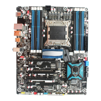
2.8.2.3 Add-in Card Connectors
The board has the following add-in card connectors:
• PCI Express x16: one connector supporting simultaneous transfer speeds up to 8 GBytes/sec.
• PCI Express x1: the D915GAV board has two PCI Express x1 connectors; the D915GAG
board has one PCI Express x1 connector. The x1 interfaces support simultaneous transfer
speeds up to 500 MBytes/sec.
• PCI Conventional (rev 2.2 compliant) bus: the D915GAV board has four PCI Conventional
bus add-in card connectors; the D915GAG board has two PCI Conventional add-in card
connectors. The SMBus is routed to PCI Conventional bus connector 2 only (ATX expansion
slot 6). PCI Conventional bus add-in cards with SMBus support can access sensor data and
other information residing on the Desktop Board.
Note the following considerations for the PCI Conventional bus connectors:
• All of the PCI Conventional bus connectors are bus master capable.
• SMBus signals are routed to PCI Conventional bus connector 2. This enables PCI
Conventional bus add-in boards with SMBus support to access sensor data on the boards. The
specific SMBus signals are as follows:
⎯ The SMBus clock line is connected to pin A40.
⎯ The SMBus data line is connected to pin A41.
NOTE
The PCI Express x16 connector is configured to support only a PCI Express x1 link when the
Intel GMA900 graphics controller is enabled.