14
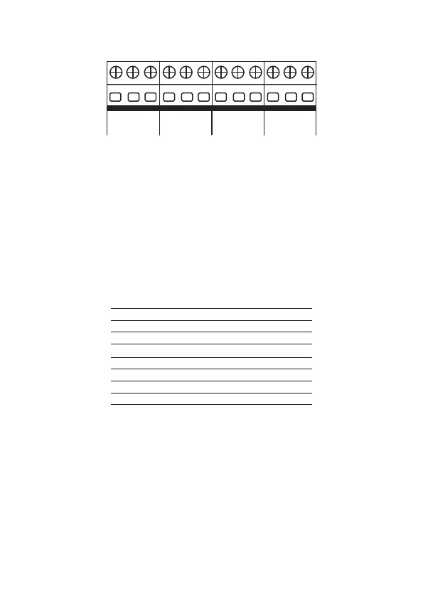
1.10. Zone/sector input
J10 J9 J11 J12
Z1 COM. Z2
(Z11) (Z12)
ZONES
Z3 COM. Z4
(Z13) (Z14)
ZONES
Z5 COM. Z6
(Z15) (Z16)
ZONES
Z7 COM. Z8
(Z17) (Z18)
ZONES
Input for connecting the wired sensors, where a 4×26 AWG or higher cable with a
maximum length of 100 m and a total resistance of 40 must be used.
These terminals are divided into groups of three, with the common (COM, in the
middle) and zone inputs (Z1, Z2, Z3, Z4, Z5, Z6, Z7 and Z8, on the sides).
If you are using Single Zones, the zone number is what is described next to the word
COM
.
For example, in the last terminal block we have Z7 (Zone 7), COM (Common) and
Z8 (Zone 8). If congured as Dual Zones, use the following chart to identify the high
zones.
Input terminal Dual zone number
Z1 Zone 11
Z2 Zone 12
Z3 Zone 13
Z4 Zone 14
Z5 Zone 15
Z6 Zone 16
Z7 Zone 17
Z8 Zone 18
Note:
the sensor connected to the 2K2 resistor becomes zone 1, the sensor con-
nected to the 3K9 resistor becomes zone 11.
The system supports eight different combinations numbered 0 to 7 and are chosen
through programming. The chosen conguration is valid for all the panel’s zones,
except for the keyboard zones. For each of the combinations it is necessary to follow
a connection scheme for the sensors.
Note
:
to guarantee the correct operation in all the connection types presented be-
low, all the resistors must be installed close to the sensor and not directly in the
center’s zone terminal block, because this will not be useful and the system’s security
will be compromised.