9
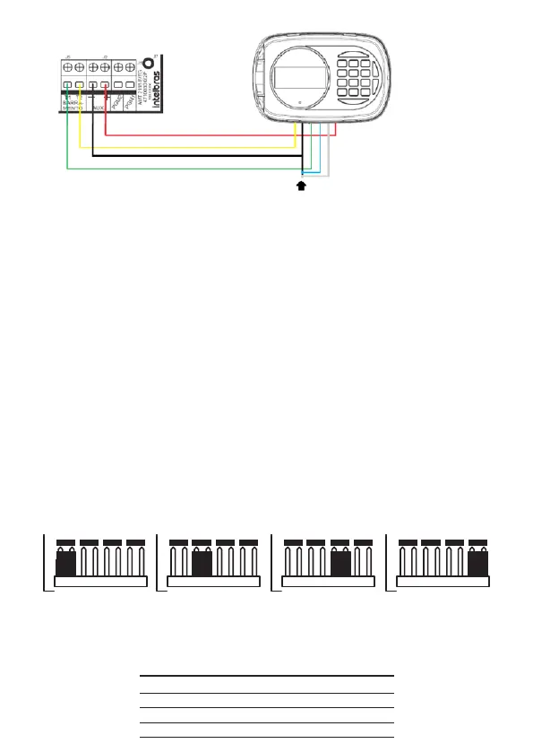
To cancel the keyboard zones connect the blue and white wire to the black wire of the 6 way cable
The Vdc +12 V power supply, red wire, of the keyboards should be connected to the
AUX+ point of the alarm center. The grounding, black wire, for the keyboards must
be connected to the center’s AUX- point. As for the busbars T1, green wire, and T2,
yellow wire, from the keyboards must be connected to points T1 and T2 of the alarm
center units, respectively.
Note:
»
The keyboard zones (Zone 09 and Zone 10) behave as single zones, they
can’ t be duplicated.
»
We recommend that you do not use external power supplies to feed the devi-
ces connected to bus T1 and T2, their power supply must be connected to the
center’s AUX output.
»
If it is necessary to use an external power supply for powering some device on
bus T1 and T2, it must be connected the Negative (-) of the power supply in
common with the Negative of the Auxiliary Output of the center (AUX -).
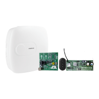
Keyboard addressing jumper
A maximum of 4 keyboards may be connected per center. The jumper’s position in the Address
connector denes which will be Keyboard 1, Keyboard 2, Keyboard 3, and Keyboard 4.
4
3
2
1
4
3
2
1
4
3
2
1
4
3
2
1
Keyboard 4 Keyboard 3 Keyboard 2 Keyboard 1
Address
Address
Address
Address
The following table shows the identications of the zones according to the addres-
sing of the keyboard jumper.
Keyboard Blue Wire White Wire
Keyboard 1 Zone 09 Zone 10
Keyboard 2 Zone 19 Zone 20
Keyboard 3 Zone 21 Zone 22
Keyboard 4 Zone 23 Zone 24