23
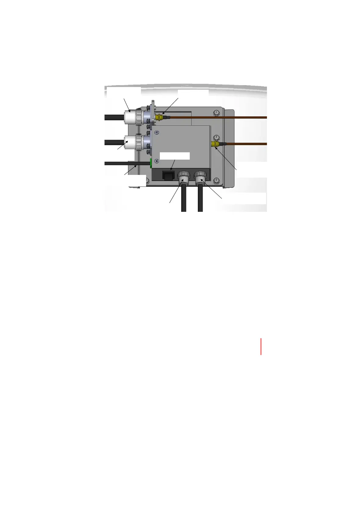
RF Cable Connections
Ensure that the power switch is off during the installation period and all
the cables are connected properly between the antenna control unit and
the power switch box. When all the hardware and cable have been
installed, turn on the power switch. Use RG11 rubber gland if you’re
using RF11 cable instead of RG6 supplied by Intellian.
Rotary #2
Rx Cab le
(From Antenna)
BUC Power Cable(OUT)
(From Antenna)
Antenna Power Cable
(From Antenna)
On/ Of f Switch
Modem Tx Cable
(From outside)
ACU Rx Cab le
(From outside)
Rotary #1
Tx Cab l e
(From Antenna)
BUC Power Cable(IN)
(Fro m ACU)
Front View
Figure 20. Cable Connections on Power Switch Box
Installing the Antenna
 Loading...