Do you have a question about the Intellian v60E and is the answer not in the manual?
Defines WARNING, CAUTION, and NOTE statements used in the manual for safety and critical information.
Emphasizes reading and understanding all safety requirements before using the antenna.
Details Intellian's declaration of conformity with FCC regulations for Ku-band VSAT antennas.
Declares conformity with EU Radio Equipment Directive (2014/53/EU) and lists harmonized standards applied.
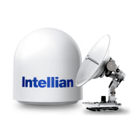
Introduces the v60E as a 3-axis stabilized VSAT maritime antenna system for efficient RF performance.
Highlights features like efficient RF performance, single coaxial cable, modular components, and AptusNX.
Guides on choosing an installation site with clear line-of-sight for optimal satellite signal reception.
Details installing the antenna to ensure maximum performance by avoiding obstacles in the beam path.
Advises on positioning the antenna away from high-power radar to prevent interference.
Warns about RF radiation exposure and specifies minimum safety distances from the antenna.
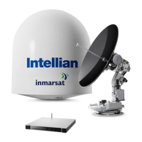
Describes the components of the system, including the Above Deck Unit (ADU) and Antenna Control Unit (ACU).
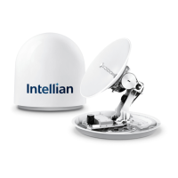
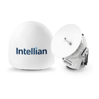
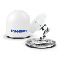
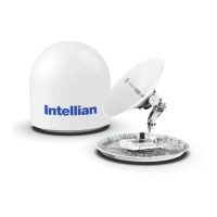
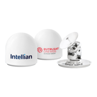
Details the ADU, which includes the antenna pedestal and radome, protecting it from the marine environment.
Explains the ACU's role in controlling the antenna system and its supported functions.
Lists all components included in the system package for installation.
Details requirements for customer-supplied RF and Gyrocompass cables.
Specifies coaxial cable types, connector requirements, and cable length considerations.
Recommends NMEA 0183 gyrocompass cable types and connection details.
Provides step-by-step instructions for safely unpacking the system components.
Shows the physical dimensions of the antenna unit, including height and diameter for installation planning.
Illustrates the real-size mounting template for drilling holes on the mast to match the antenna.
Guides on mast design, considering plate thickness and recommended bolt sizes for secure antenna mounting.
Details the recommended mast size and configuration for routing cables internally.
Details the recommended mast size and configuration for routing cables externally.
Provides instructions on routing RF cables through or on the mast, ensuring watertight connections.
Details routing the RF cable inside the mast and securing it with cable ties.
Details routing the RF cable on the outside of the mast and securing it with cable ties.
Provides step-by-step instructions for safely detaching the antenna from its shipping pallet.
Guides on lifting and positioning the antenna onto the mast, ensuring sufficient clearance for cabling.
Explains how to insert waterproof foam to prevent water penetration into the radome before mounting.
Details the process of securely mounting the antenna onto the mast using bolts and a torque wrench.
Provides instructions on connecting the RF cable to the antenna's radome connector.
Details terminating the RF cable's N-connector and securing the connection.
Guides on choosing a suitable location for the ACU below deck, ensuring it is dry and accessible.
Provides the physical dimensions of the Antenna Control Unit (ACU) for installation planning.
Explains how to mount the ACU into a standard 19-inch rack using provided brackets.
Details the required components and their connections for a basic VSAT antenna system.
Describes the basic system setup involving one VSAT antenna and one ACU.
Outlines the procedures for connecting various cables to the ACU.
Identifies and illustrates the connectors located on the back panel of the ACU.
Provides pinout information for the ACU's power connector.
Details the pinouts and functions for the Modem Rx/Tx connectors.
Details the pinouts and functions for the Antenna RF N-Type Female connector.
Details the pinouts for the NMEA 0183 Gyrocompass input terminal block.
Provides pinout details for the RS232/RS422 modem interface connector.
Provides pinout details for the modem console interface connector.
Provides pinout details for the RS232 PC interface connector.
Provides pinout details for the RJ-45 LAN connector.
Guides on connecting the ACU to a power supply using the provided power cord.
Details connecting the RF cable from the ACU's ANTENNA port to the radome's RF port.
Explains how to connect the ACU to the modem using RF and Ethernet cables.
Guides on connecting a gyrocompass to the ACU's NMEA 0183 input for satellite tracking.
Provides detailed steps for connecting the NMEA 0183 gyrocompass cable to the terminal block.
Outlines methods for establishing communication between the ACU and a PC.
Details setting up communication via Ethernet using the management LAN port.
Explains establishing PC communication using the ACU's front panel USB port.
Instructions on powering on the system and waiting for the satellite lock indicator.
Guides on accessing the AptusNX web interface via TCP/IP connection.
Details configuring the modem settings within the AptusNX interface.
Describes confirming the iARM save and reboot process through a pop-up window.
Introduces the Install Wizard for system commissioning and initial setup.
The initial welcome screen of the Install Wizard, prompting to proceed to the next step.
Guides on confirming the GPS status and setting the vessel's position for satellite searching.
Instructions for setting the ship's heading device and connection status.
Guides on selecting the modem type and confirming the modem connection status.
Details methods for setting the bow offset by selecting a trackable satellite.
Describes setting bow offset using the Beam Switch tracking type.
Describes setting bow offset using the Library tracking type.
Explains setting blockage zones to create transmission mute sectors for safety.
Guides on selecting the target satellite for tracking.
Describes selecting the target satellite via modem control.
Guides performing a line-up test to confirm antenna performance with the satellite operator.
Details the line-up test procedure for iDirect Open AMIP modems.
Explains modem information, transmit control settings, antenna angle, and test result inputs.
Details the line-up test procedure for modems other than iDirect Open AMIP.
Describes viewing and saving the configuration report from the installation wizard.
Identifies and explains the components and LED status indicators on the ACU's front panel.
Introduces AptusNX software for remote monitoring, control, and diagnosis of the antenna.
Guides on connecting to the ACU's AptusNX web interface via IP address.
Details the AptusNX login process and different user access levels.
Explains the main menus and their functions within the AptusNX interface.
Describes managing user accounts, including password changes and session timeouts.
Details changing passwords and setting session timeouts for user accounts.
Guides on registering product, vessel, and service provider information for customer service.
Displays system information, including antenna, S/W version, and network IP address details.
Explains how to add, manage, and set permissions for different user accounts.
Introduces the Dashboard for quick monitoring and arranging status panels.
Guides on customizing the dashboard by adding or removing information panels.
Explains how to rearrange panels on the dashboard for a customized layout.
Details using shortcut buttons on dashboard panels to access detailed settings.
Refers to the previous section for detailed instructions on using the Install Wizard.
Covers firmware upgrade, iARM upgrade, save/reboot, satellite library, and graph functions.
Guides on upgrading antenna firmware using manual or auto methods.
Step-by-step instructions for performing a manual antenna firmware upgrade.
Details the process of upgrading the iARM module firmware.
Step-by-step instructions for uploading and installing iARM firmware files.
Explains how to save iARM settings and reboot the system.
Covers reading, managing, and loading satellite information from the library.
Explains how to view and customize graphs for signal level, antenna angles, and other parameters.
Covers diagnosis, antenna logs, event logs, and support resources.
Guides on executing antenna diagnosis tests to check system status.
Details viewing, saving, printing, and clearing diagnosis results.
Explains how to access and download antenna log data and firmware logs.
Guides on setting options to display and query antenna event log information.
Provides access to manuals, support desk, and frequently asked questions (FAQ).
Covers setting up Ship, Antenna, Satellite, Network, Modem, and Backup/Restore functions.
Details setting ship information, GPS, heading device, and block zones.
Explains detailed settings for GPS, heading, bow offset, and blockage zones.
Guides on setting antenna position, search parameters, and sensor calibration.
Details settings for antenna angle, thresholds, search parameters, and conical range.
Explains tilt sensor bias, LNB pol calibration, and antenna mode settings.
Guides on setting current tracking satellite, NBD, Eutel satellite, and modem lock.
Details managing network interface, services, sys log, and radius settings.
Provides detailed settings for network services, system logs, and radius authentication.
Guides on selecting modem type, configuring ports, and managing modem connection.
Details modem parameters like IP address, routing, ports, and protocols.
Explains modem connection, beam selection, and Newtec modem monitoring options.
Guides on backing up and restoring antenna and iARM settings.
Lists detailed technical specifications for the antenna system.
Details ACU size, weight, interfaces, and power requirements.
Lists operational and survival specifications for temperature, vibration, shock, and waterproofing.
Outlines the warranty coverage for parts and labor, and conditions for warranty application.
Provides recommended tightening torque values for various bolt sizes.
| Frequency Band | Ku-band |
|---|---|
| Antenna Diameter | 60 cm |
| Tracking | Automatic |
| Data Rate | Up to 50 Mbps |
| Type | VSAT Antenna |
| Polarization | Linear |
| Azimuth Range | 360 degrees |
| Ship Motion | Roll: ±25°, Pitch: ±10° |
| Operating Temperature | -25 to +55 °C |
| Input Power | 100-240 VAC, 50/60 Hz |
| Stabilization | 3-axis |
| Humidity | Up to 100% |
| Power Supply | 24V DC |