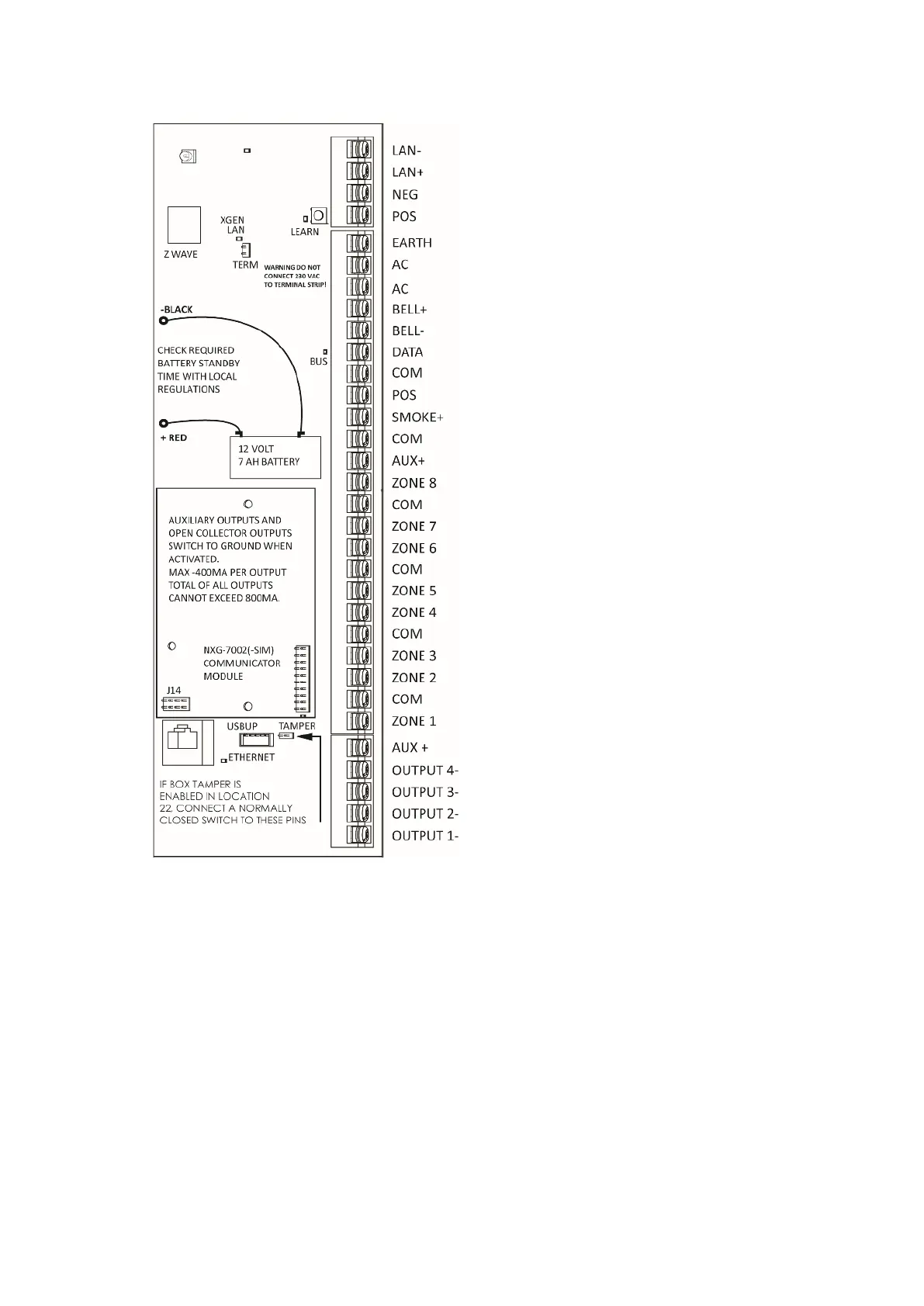
Top to bottom:
LAN-, LAN+, NEG, POS: Terminals for
xGenLite RS485 bus.
LEARN: Enrollment button, hold down for 3 s to
activate automatic device enrollment
feature.
TERM: Term link for xGenLite RS485 bus.
A TERM link should be installed on the two
furthest devices.
EARTH, AC, AC: Connect transformer (16 VAC
1.5 A) to terminals for power.
−BLACK, +RED: Connect leads to 12V Sealed
Lead Acid backup battery.
BELL+, BELL−: Connect to external 12V siren
or internal piezo screamer.
DATA, COM, POS: NetworX 3-wire bus for
legacy modules and keypads.
SMOKE-, AUX+: Two or four wire smoke
detectors, NXG-8 supports two wire smoke
detectors and will drop power to the
SMOKE- terminal to perform smoke alarm
verification.
COM, AUX+: Terminal for aux power to zones.
ZONE 1 to 8, COM – terminals to connect to
zones. Supports single EOL, zone
doubling, and dual EOL tamper monitoring.
J14: Ethernet WAN link header must be fitted if
no communicator module is installed, and
must be removed to accommodate
communicator module.
J11: Terminal to connect communicator module
to xGenLite.
Ethernet: Connect Ethernet cable to RJ45
socket to provide internet connectivity to
xGenLite.
J13: 5-pin connector used to upgrade and
program xGenLite with USBUP tool.
TAMPER: Connect to panel box tamper.
AUX+: Terminal for auxiliary power to outputs.
OUTPUT 4: Open collector output switches to
ground, follows armed state at default.
OUTPUT 3: Open collector output switches to
ground, follows ready state at default.
OUTPUT 2: Open collector output switches to
ground, follows siren state at default.
OUTPUT 1: Open collector output switches to
ground, follows strobe state at default.