14 xGen Installation & Programming Guide
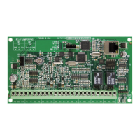
J21 USBNav
J16 SPKOutput
J1
J6
S1
D3 D10D5 D11 D12
J10J7 J13 J18 J20
D13
D15
D14
D18
D16
D17
D6 D9
J5Term
D20
J19J17J15J11J8J4J3
OP4- on J10
POS on J10
3.3K
COM
ZONE
-
+
680Ohm
-+
+
-
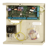
12V 7A
1...2...
TAMP1
Connect to main
J13
Install supplied ferrite
choke on Ethernet cable
before connecting
TAMP2
Optional tamper. Connect
to normally closed switch.
Apply wire short if not used.
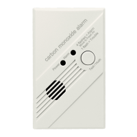
Two Wire
Smoke
Phone Line
House Phone
x2
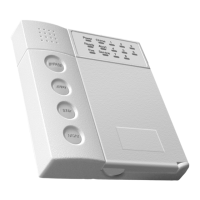
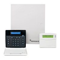
NXG-1820 Codepad
Install supplied ferrite
choke on bus cable
near codepad before
connecting
BELL
BELL
Ethernet
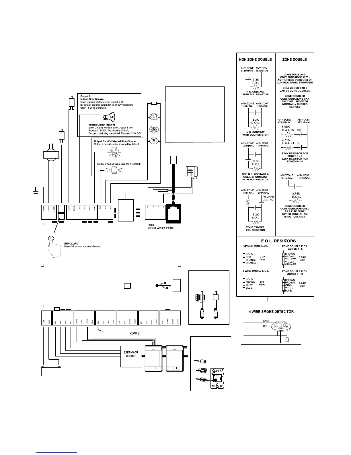
For 2-wire smoke
Enable Two Wire Smoke feature
Program Zone 8 as Fire Zone
EOL 680 ohm
For 4-wire smoke
Program Output 4 for Smoke Power
Program Zone as Fire
EOL 3K3
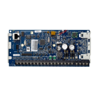
D6 Red LED – RS485 Transmitting
D9 Green LED – RS485 Receiving
D20 Red LED – Follows Output 5
panel tamper.
LEDs Bottom Row (left to right)
xGen Wiring Diagram