16 xGen Installation & Programming Guide
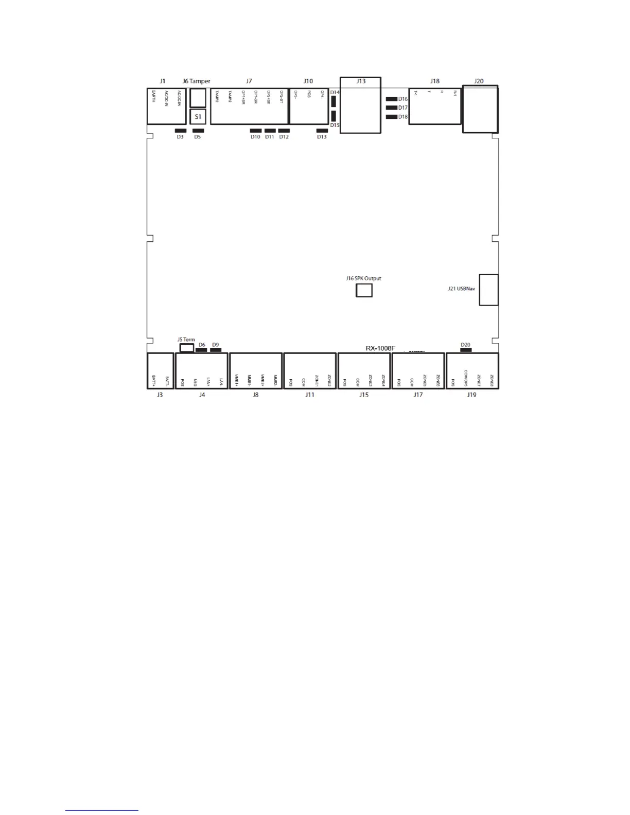
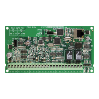
xGen Terminal Diagram
Left to right
• J1 – Terminals for power (16VAC 1.5A)
• J6 – Box Tamper
• S1 – Enrollment button, hold down for 3s to activate automatic device
enrollment feature, hold down while powering up to reset master user
• J7 – Terminals for Tamper 2, Output 1 (BELL output) and Output 2 (Outdoor
strobe)
• J10 – Terminals for Output 3 (Outdoor siren) and output 4 (power)
• J13 – RJ45 socket for IP/LAN connection
• J18 – Terminals for telephone line, bridged to J20
• J20 – RJ11 6P4C socket for telephone line, bridged to J18
• J16 – Connect to external speaker, this provides headphone level audio
output
• J21 – 5-pin connector for USBUP-EUR, used to upgrade firmware
• J3 – Terminals for backup battery
• J4 – Terminals for xGen RS-485 bus and power connection





 To Next Page