ENGLISH
31
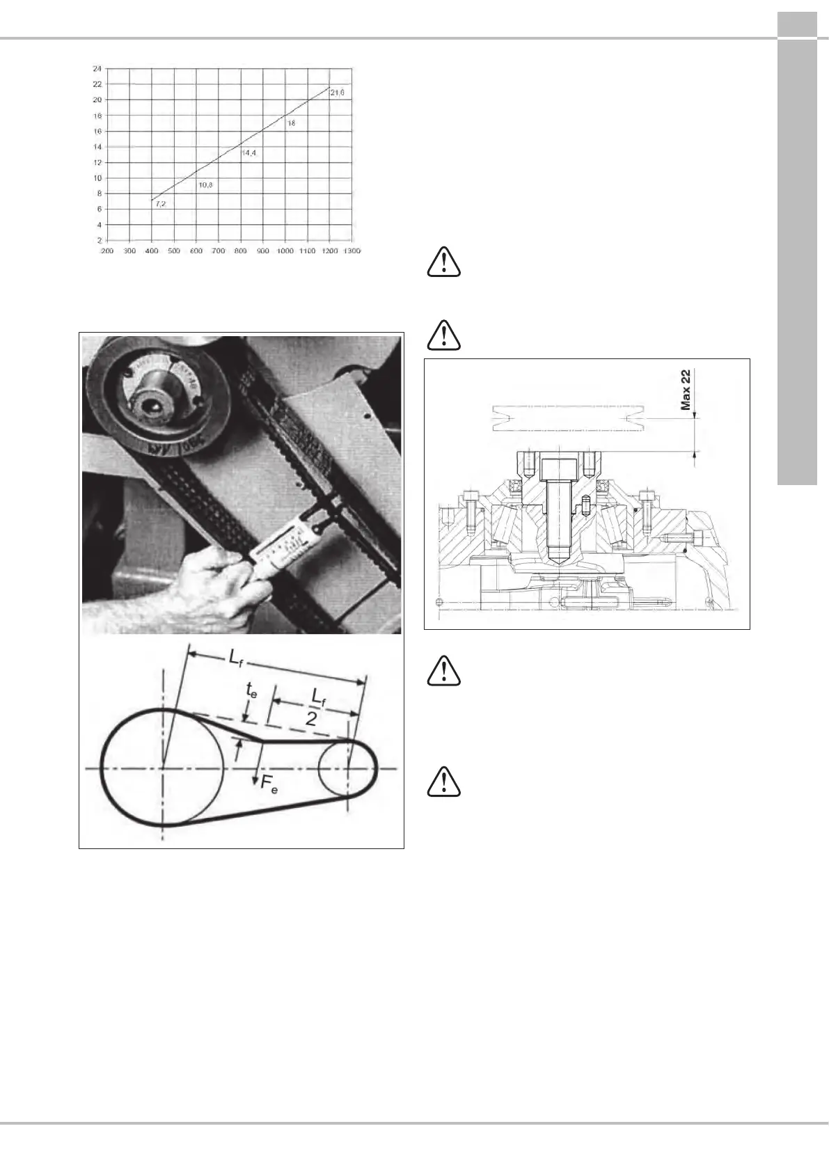
te = Belt bend mm
Lf= Wheelbase mm
Fig.12
Conclusion: with a wheelbase of 600 mm and with a
dynamometer, loading the belt branch with 75 N as indicated
in Fig.13, a "te" bend of approximately 10.8 mm is obtained.
Lf = Wheelbase
te = Belt bend
Fe = 75 N Dynamometer load
Fig.13
Note
1
. Unless otherwise stated by the supplier of the belts,
control of proper pull and its relative re-tensioning should be
performed after no less than 30 minutes of motion necessary
for the normal adjustment of the belts. Best performance and
durability will be achieved with proper tensioning.
Note
2
. In case of necessity or for routine maintenance, never
replace a single belt but the complete set.
9.13 Transmission of power from the second PTO
Upon request, the SS71, SN71 and SW71 series pumps can be
supplied with auxiliary PTO on the side opposite of the drive
(Transmission of power from the second PTO).
By means of the V-Belts, withdrawable Max Torque is:
65 Nm which corresponds to:
7 HP at 750 rpm;
7.4 HP at 800 rpm;
8.3 HP at 900 rpm;
9.3 HP at 1000 rpm;
11.1 HP at 1200 rpm.
By means of the joint, withdrawable Max Torque is:
130 Nm which corresponds to:
14 HP at 750 rpm;
14.8 HP at 800 rpm;
16.6 HP at 900 rpm;
18.6 HP at 1000 rpm;
22.2 HP at 1200 rpm.
By means of the V-belt, the transmission is
considered suitable if: belt pull is applied at a max
distance of 22 mm from the bend shaft shoulder
Fig.14. Min diameter of pulley to be used = Ø 100
mm.
With transmission by means of the joint, pay
particular attention to perfect alignment so that no
transverse forces are generated on the pump shaft.
Fig.14
For applications diering from those specied
above, contact our Technical or Customer Service
Departments.
10 START-UP AND OPERATION
10.1 Preliminary checks
Before start-up, ensure that:
The suction line is connected and pressurized
(see par.9.4 - 9.5 - 9.6) the pump must never run
dry.
1. The suction line ensures a hermetic seal over time.
2. Any shut-o valves between the supply source and the
pump are fully open. The outlet line is free discharge, to
permit rapid expulsion of the air present in the pump
manifold and therefore facilitate fast priming.
3. All suction and outlet ttings and connections are
properly tightened.
4. The coupling tolerances on the pump/transmission axis
(half-joint misalignment, Cardan joint tilt, belt pulling,
etc.) remain within limits required by the transmission
manufacturer.
5. Oil in the pump casing is at level, veried with a dipstick
(pos., Fig.15) and exceptionally with a level indicator
(pos., Fig.15).