ENGLISH
19
Secure the PTO side ange to the casing, taking care with the
lip seal as described previously and tighten the xing screws
to the recommended torque.
Then feed the ange on the indicator side without shims in
the carter and start to move it closer, manually screwing the
M6x40 service screws in equally, with small rotations such as
to move the cover in slowly and correctly.
At the same time, check that the shaft rotates freely by turning
it manually.
Continuing the procedure in this way, a sudden increase in
hardness during shaft rotation will soon be experienced.
At this point, halt the forward movement of the cover and
loosen the xing screws completely.
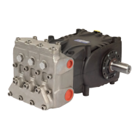
With the aid of a feeler gauge, measure the clearance between
the side cover and pump casing (see Fig.14).
Fig.14
Proceed to determine the shim pack, using the table below:
Detected Measurement Shim Type No. of pieces
From: 0.05 to: 0.10 / /
From: 0.11 to: 0.20 0.1 1
From: 0.21 to: 0.30 0.1 2
From: 0.31 to: 0.35 0.25 1
From: 0.36 to: 0.45 0.35 1
From: 0.46 to: 0.55
0.35
0.10
1
1
From: 0.56 to: 0.60 0.25 2
From: 0.61 to: 0.70
0.35
0.25
1
1
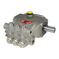
Fig.15
Once the type and number of shims have been determined
using the table, check the following: assemble the shim pack
on the indicator side cover centering (Fig.15), secure the cover
to the casing, following the procedure in par.2.1.2, and tighten
the screws to their recommended torque.
Check that the shaft rotation stall torque is between 4 Nm and
6Nm.
If this torque is correct, connect the con-rods to the bend
shaft and to the next stages. If it is not, redene the shim pack,
repeating the operations.
2.2 REPAIRING HYDRAULIC PARTS
2.2.1 Disassembly of the head-valve units
Operations are limited to inspection or replacement of valves,
if necessary.
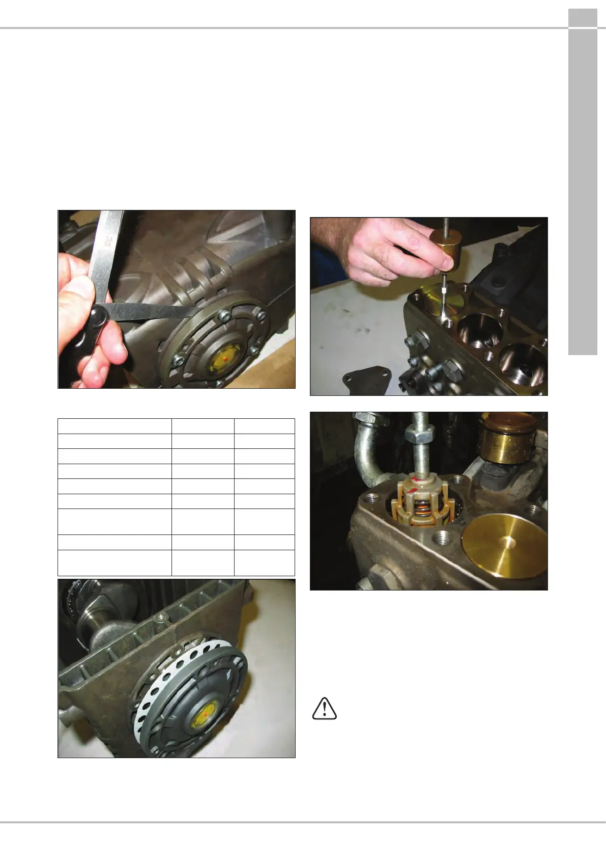
Proceed as follows to extract the valve units:
Fig.16
Fig.16/a
- Unscrew the 7 M12x35 valve cover xing screws and
remove the covers (Fig.16).
- Remove the valve plugs by means of an extractor hammer
(code 26019400 combined with the tool code 27513600,
Fig.16).
- Extract the valve units using the same extractor hammer
used for the valve plugs (code26019400 combined with
the tool code 27513600, Fig.16/a).
If the suction and outlet valve seats remain
stuck on the head (for example because of
incrustations due to prolonged lack of use of the
pump), proceed as follows:
- use the extractor tool (code 27516900 combined
with the tool code 26019400, Fig.16/b).