ENGLISH
20
code 26019400
code 27516900
Fig.16/b
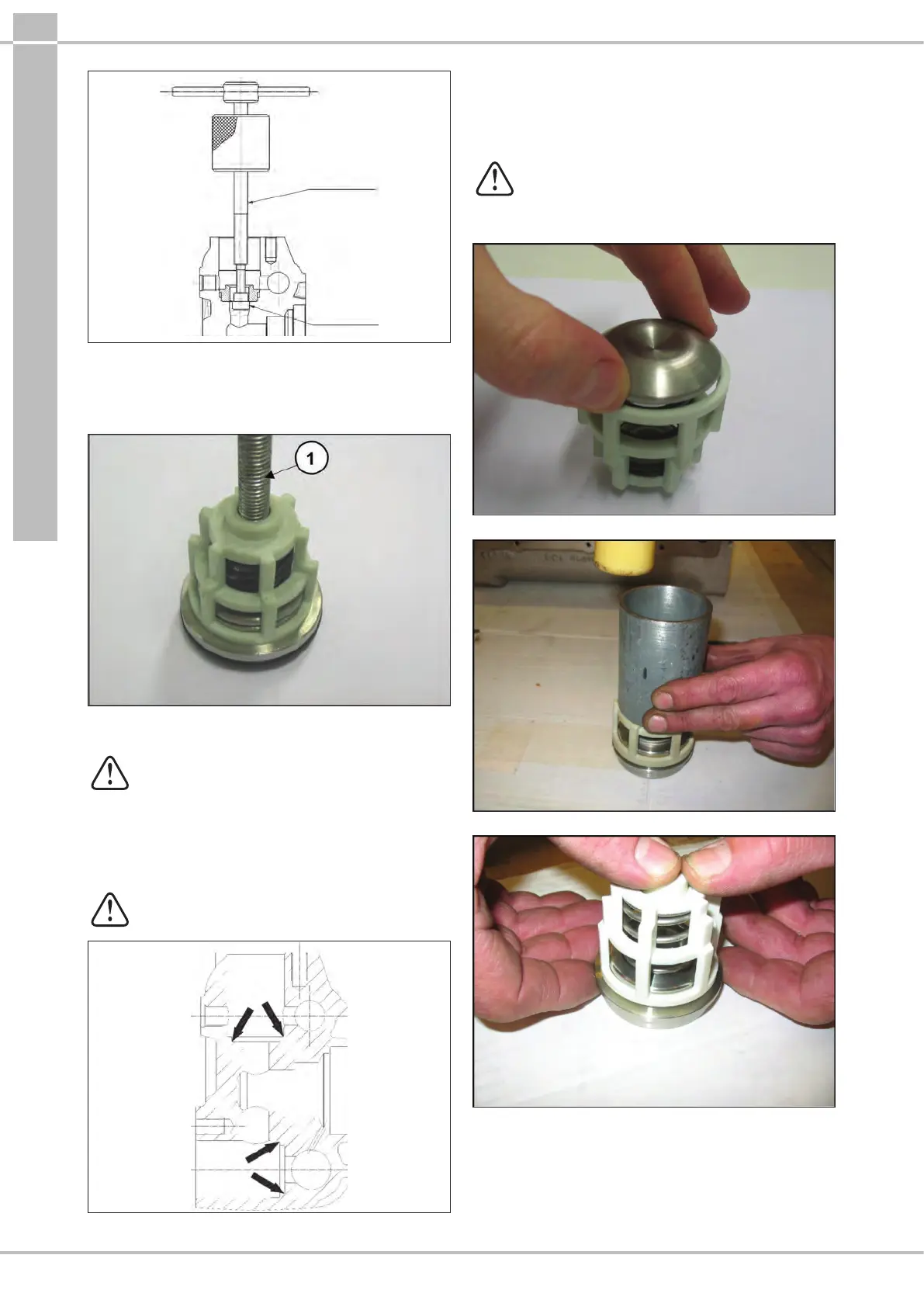
- Disassemble the suction and outlet valve units, screwing a
suciently long M10 screw in such a way as to be able to
reach the valve plate and extract the valve guide from the
valve seat (pos. , Fig.17).
Fig.17
2.2.2 Reassembly of the head – valve units
Pay particular attention to the conditions of the
various components and replace if necessary,
and at the intervals indicated in the “PREVENTIVE
MAINTENANCE” table in the use and maintenance
manual.
At every valve inspection, replace all O-rings and
all anti-extrusion rings both in the valve units
and on the valve plugs.
Before repositioning the valve units, thoroughly
clean and dry the relative seats in the head as shown
in Fig.18.
Fig.18
To reassemble the various components, perform the
operations listed above in reverse order to par.2.2.1.
Tofacilitate insertion of the valve guide in its housing, you can
use a bush resting on the horizontal guide planes and use a
hammer acting on the whole circumference (Fig.19/a).
Do not invert the suction springs with the
previously disassembled outlet springs during
assembly of the suction and outlet valve units:
A) “White” suction springs.
B) “Black” outlet springs.
Fig.19
Fig.19/a
Fig.19/b