ENGLISH
27
3. Completely airtight and constructed to ensure a perfectly
hermetic seal through time.
4. Prevent the pump from emptying when it is stopped,
including partial emptying.
5. Do not use 3 or 4-way hydraulic ttings, adapters, swivel
joints, etc. as they could jeopardize pump performance.
6. Do not install Venturi tubes or injectors for detergent
suction.
7. Avoid use of foot valves or other types of unidirectional
valves.
8. Do not recirculate the by-pass valve drain directly to the
suction line.
9. Provide for proper guards inside the tank to prevent that
water ow from the bypass and the tank supply line can
create vortexes or turbulence near the pump supply pipe
port.
10. Make sure the suction line is thoroughly clean inside
before connecting it to the pump.
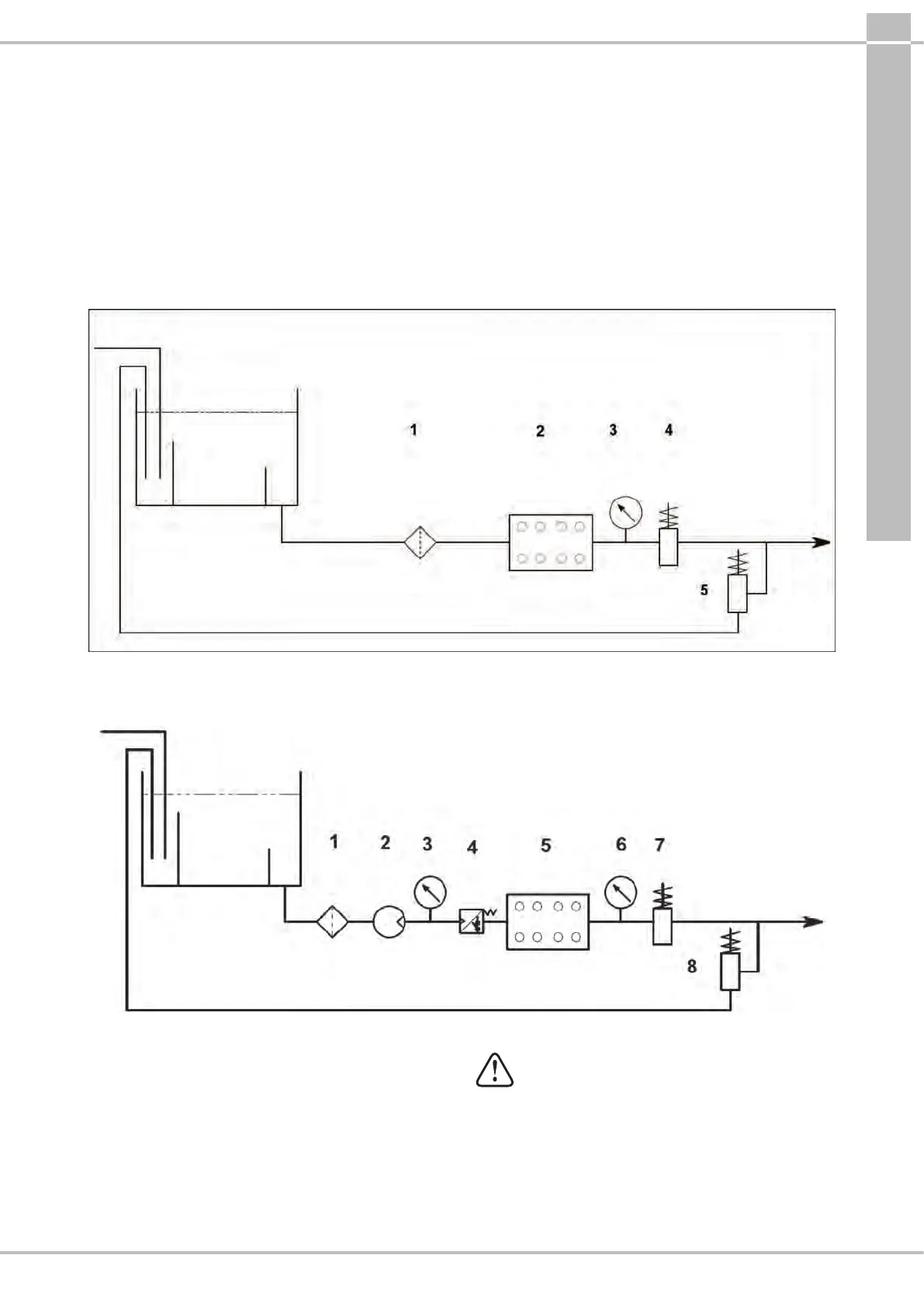
9.7 Filtration
1 lter must be installed on the pump suction line, positioned as indicated in Fig.7 and Fig.7/a.
With uid at ambient temperature
1 Filter 1
2 Plunger pump
3 Pressure gauge
4 Safety valve
5 Manual control valve
Inlet
Supply tank
Bypass
Fig.7
With uid at high temperature max. 85° C
1 Filter
2 Booster Pump
3 Pressure gauge
4 Pressure switch
5 Plunger pump
6 Pressure gauge
7 Safety valve
8 Manual control valve
Inlet
Supply tank
Bypass
Fig.7/a
The lter, which is to be installed as close to the pump as
possible, must be easily inspectable and have the following
specications:
1. Minimum ow rate at least 3 times the nominal ow rate
of the pump.
2. Inlet/outlet port diameters no smaller than the inlet port
diameter of the pump.
3. Filtration grade between 200 and 360 µm .
For smooth pump operation, regular lter
cleaning is necessary, planned according to the
actual use of the pump in relation to the quality
of water used and actual clogging conditions.
9.8 Outlet line
For correct design of the outlet line comply with the following
installation prescriptions:
1. The internal diameter of the pipe must be sucient to
ensure correct uid velocity, see graph in par.9.9.