ENGLISH
17
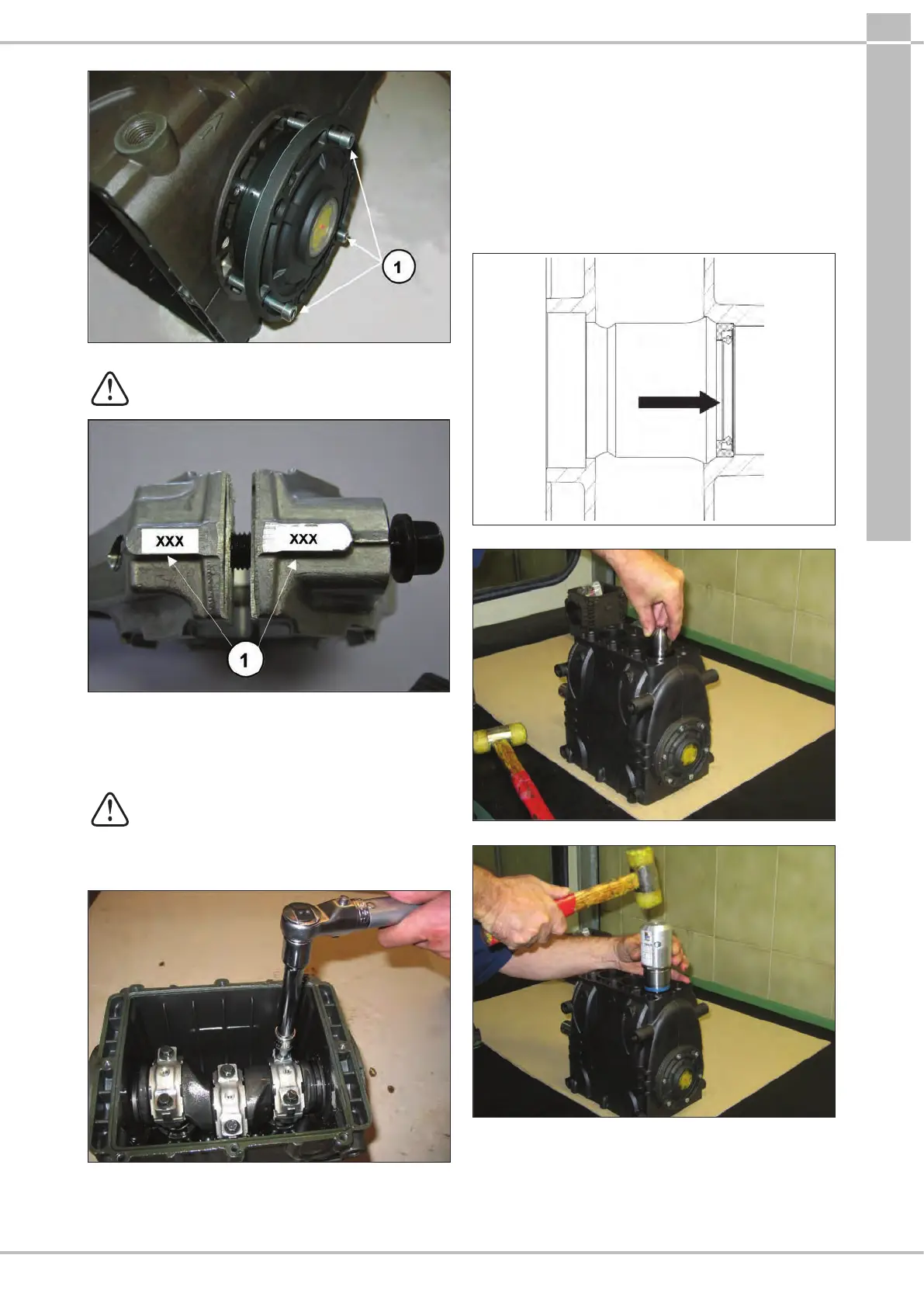
Fig.8
- Couple the con-rod caps to their shanks,
referring to the numbering (Fig.9, pos.).
Note the correct assembly direction of the caps.
Fig.9
- Fasten the caps to their respective con-rod shanks by
means of M8x1x48 screws (Fig.10) lubricating both the
underhead and the threaded shank, proceeding in two
dierent stages:
1. Manually turn the screws until they begin to
tighten
2. Tightening torque 30 Nm
Alternatively, ensure:
1. Pre-tightening torque 10-15 Nm
2. Tightening torque 30 Nm
Fig.10
- After having completed tightening operations, check that
the con-rod head has a side clearance in both directions.
- Insert the new piston guide seal rings as far as possible
into the relative seat on the pump casing (Fig.11),
following the procedure described:
use the tool code 27904900 composed of a tapered bush
and a buer. Screw the tapered bush into the hole in the
piston guide (Fig.11/a), insert the new seal ring on the
buer as far as it will go (determined by the height of the
buer) into its seat on the pump casing (Fig.11/b), remove
the tapered bush (Fig.11/c).
POS. RING
Fig.11
Fig.11/a
Fig.11/b