19
Version 2.0 (11/2013) en
Translation of the original instructions
DriveControl DC-20/DC-54
Assembly
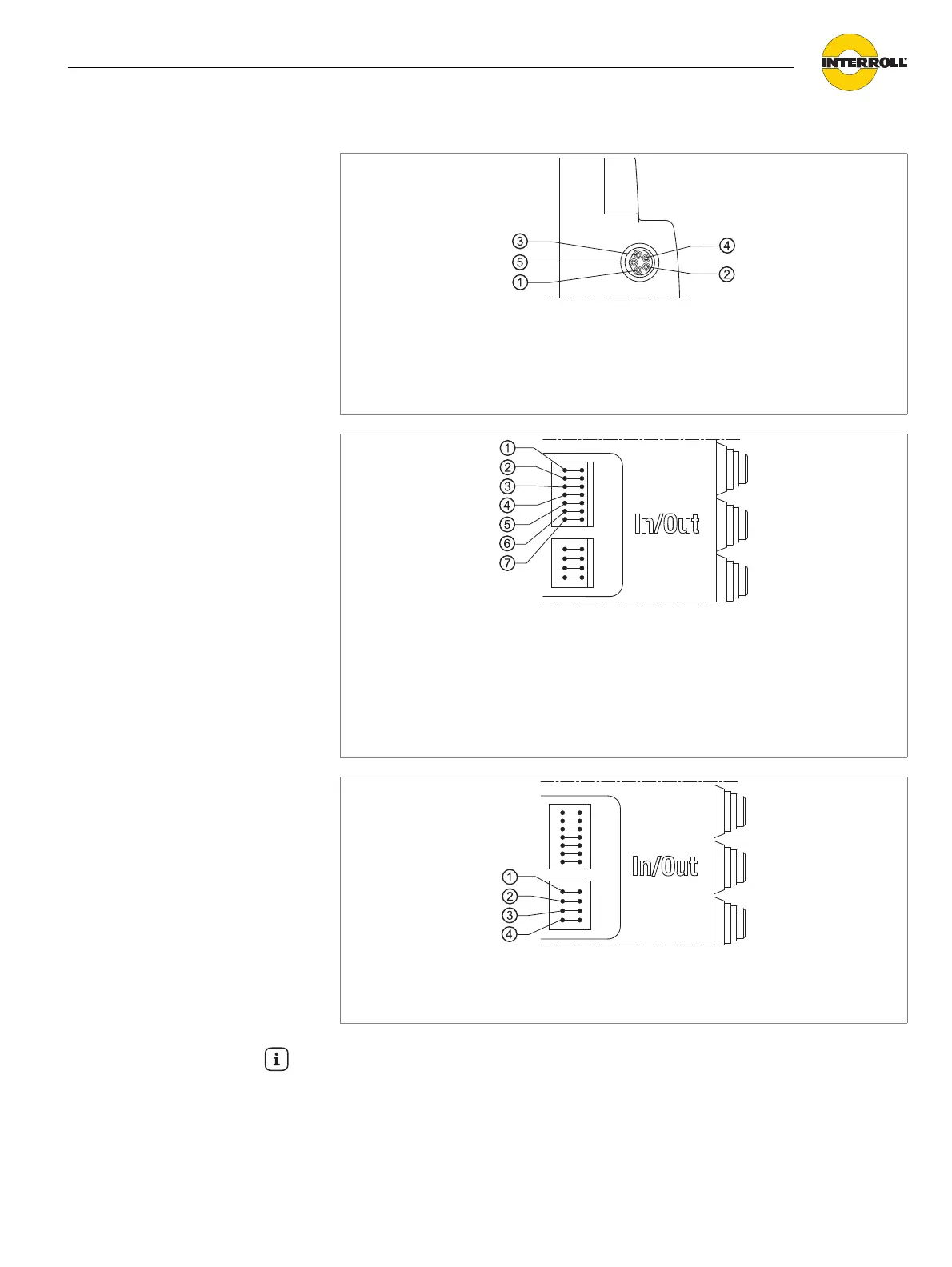
DriveControl 54
The electrical data of each connection are specified in the appendix (see
"Electrical data of connectors", page 30).
Connection RollerDrive: 8 mm snap-in, 5 poles, contact configuration
according to DIN EN 61076-2
1 +24 V DC
2 Output for rotation direction
3 Earth
4 Input for fault
5 Output for speed
Connection of inputs/outputs
1 COMMON GND (common signal
earth)
2 24 V EXT (Power supply for signal
ERROR)
3 ERROR (Output for fault)
4 DIR (Rotation direction)
5 SPEED C (Input for speed setting)
6 SPEED B (Input for speed setting)
7 SPEED A (Input for speed setting)
Power supply connection
1 GND (Earth)
2 +24 V DC
3 GND (Earth)
4 +24 V DC
Hint
The power supply connection is double. Both connections are directly interconnected
internally. The power supply can be implemented with a DriveControl so that a
maximum of two DriveControls can be connected in sequence.