20
Version 2.0 (11/2013) en
Translation of the original instructions
DriveControl DC-20/DC-54
Assembly
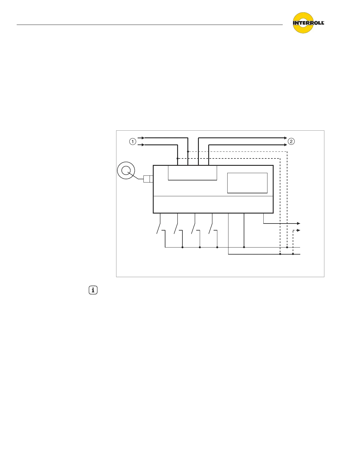
Wiring diagrams
The signals SPEED A, SPEED B, SPEED C, DIR and ERROR are completely
electrically isolated from the operating voltage via optocouplers. The output
signal ERROR additionally requires the external voltage 24 V EXT. The common
earth connection of signals SPEED A, SPEED B, SPEED C, DIR and ERROR is
COMMON GND.
If electrical isolation is not required, the 24 V connections (power supply) can be
connected with 24 V EXT (inputs/outputs) and GND (power supply) can be
connected with COMMON GND (inputs/outputs).
Basic circuit
1 Operating voltage of power supply unit (conductor 1.5 mm
2
, AWG 16)
2 Additional DriveControl (conductor 1.5 mm
2
, AWG 16)
SPEED
A
Common
GND 24 V EXT ERROR
10A
DriveControl
ERROR
+
-
+
-
24 V EX
GND +24V +24V GND
DIR
CB
Hint
The dotted conductors are only used if electrical isolation is not required between
the inputs/outputs and the operating voltage.