21
Version 2.0 (11/2013) en
Translation of the original instructions
DriveControl DC-20/DC-54
Assembly
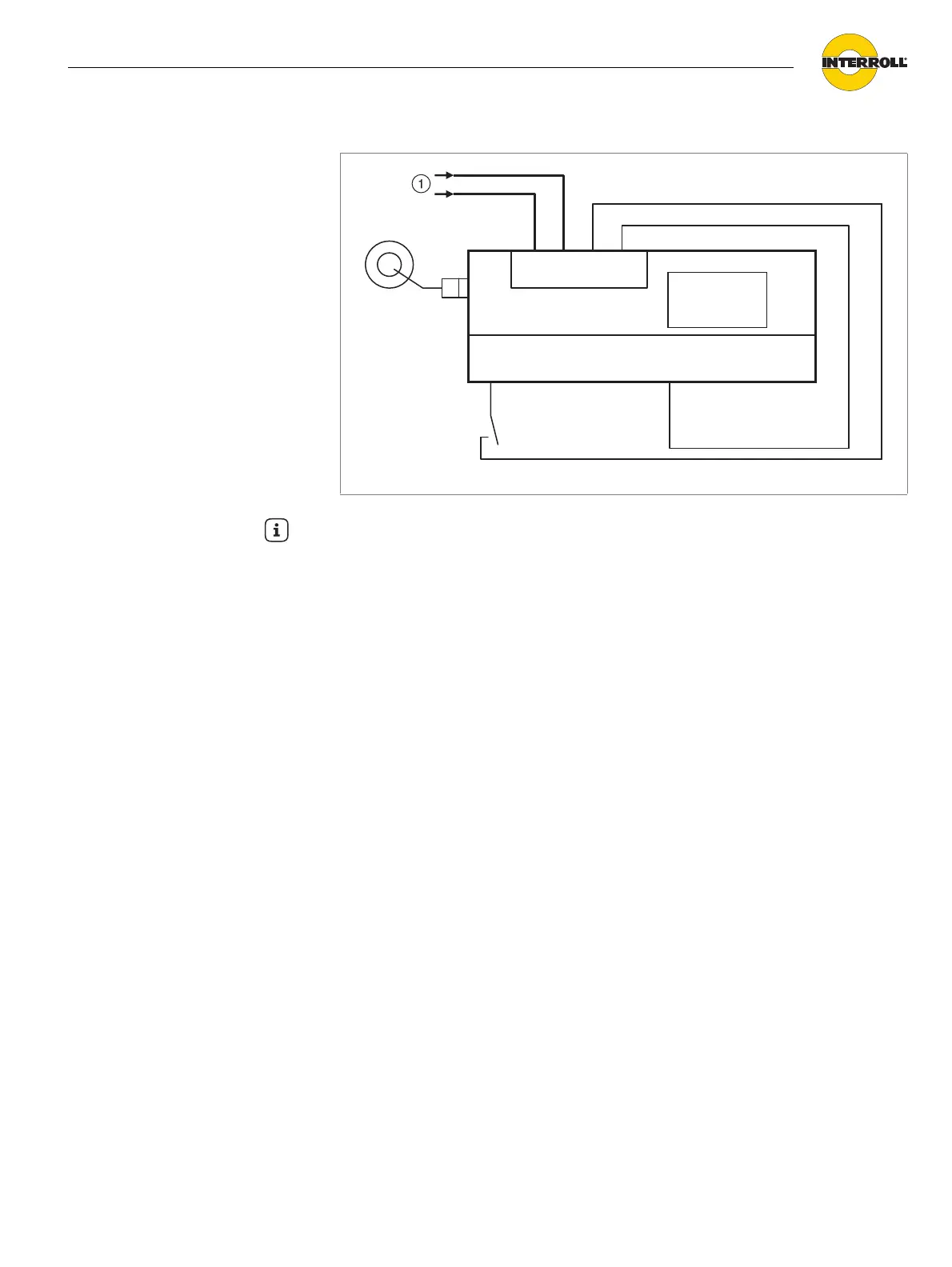
Minimum circuit
1 Operating voltage of power supply unit (conductor 1.5 mm
2
, AWG 16)
SPEED
A B C DIR
Common
GND
24 V EXT
ERROR
+
-
GND +24V +24V GND
DriveControl
Hint
• This switching enables the specification of the nominal values for speed and
rotation direction via the internal DIP switches.
• The error signal is not used, faults are only displayed via the red LED.
• Start and stop can be controlled by changing the level at the SPEED A
connection.
• The DriveControl or RollerDrive must not be switched on or off via the
activation or deactivation of the DriveControl power supply; this may only be
implemented via the start signal (SPEED A, B, C).