22
Version 2.0 (11/2013) en
Translation of the original instructions
DriveControl DC-20/DC-54
Assembly
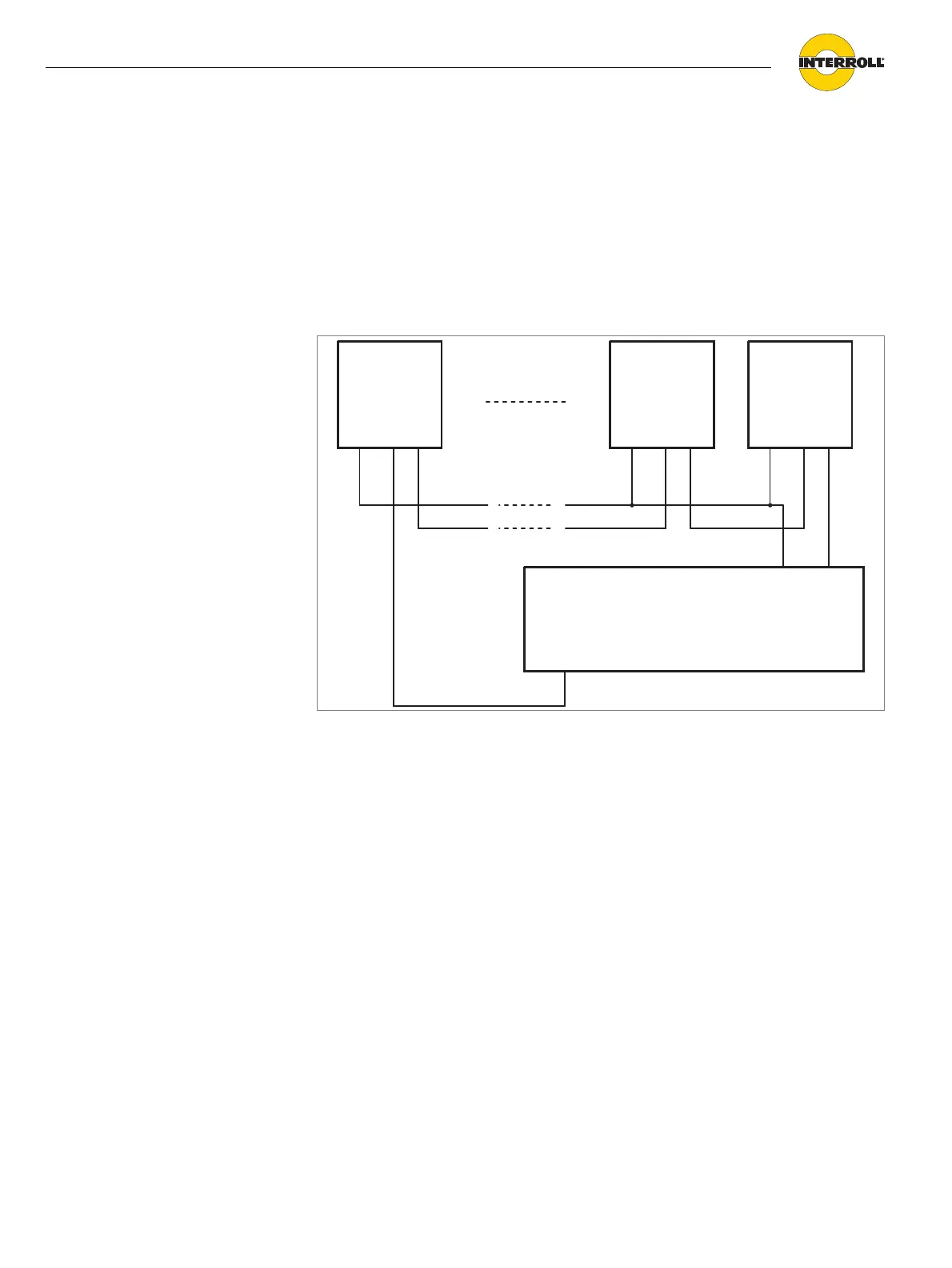
Error signal connection To evaluate the error signal, the input 24 V EXT must be supplied with a voltage
of 24 V DC.
Connect input 24 V EXT with the operating voltage.
The error signal of a maximum of six DriveControls can be linked via series
switching. The logic level "no error" is hereby reduced by 1.1 V per DriveControl.
Connect output ERROR of the previous DriveControl with the input 24 V EXT
of the following DriveControl.
When operating voltage is disconnected, the ERROR output switches to the error
condition. This ensures correct display of faults when the error signal of several
DriveControl has been linked and the operating voltage of a DriveControl is
switched off or if a cable defect (e.g. loosened contact, cable rupture) occurs.
When operating voltage is switched on, the error signal is active until the internal
microcontroller assumes control. If no error exists, the error signal is canceled
approx. 400 ms after activating the operating voltage.
PLC
IN X.X
GND
24 V
Common GND
ERROR
24 V EXT
DriveControl DriveControl DriveControl
Common GND
ERROR
24 V EXT
Common GND
ERROR
24 V EXT