52
OPERATION AND SETUP WITH THE APP
inVENTer Connect controller platform | Operating instructions
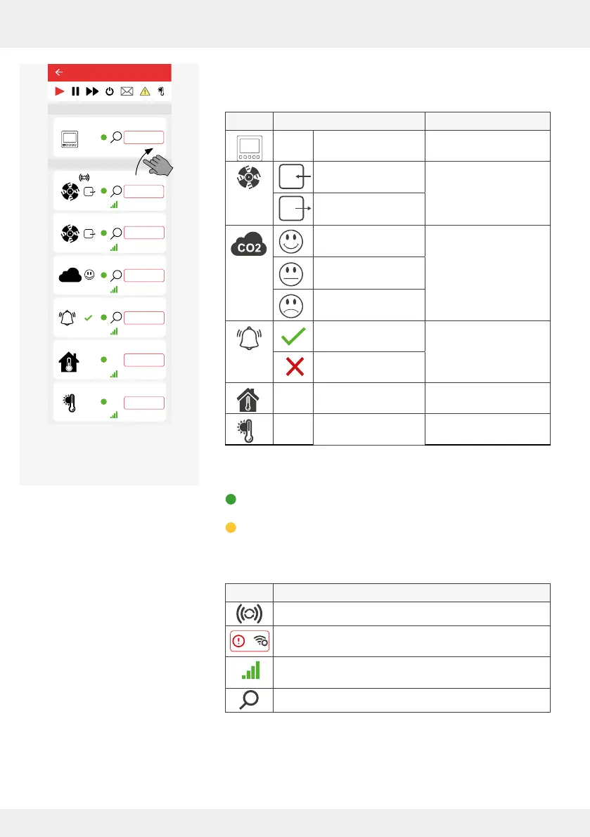
The following device symbols and statuses are displayed as
soon as the associated component is paired:
Symbol Status Paired component
Transmitted tempera-
ture and humidity
Controller
Fan with direction of
rotation supply air
Inner cover
[ventilation unit]
Fan with direction of
rotation exhaust air
CO
2
content
Good
CO
2
sensor
CO
2
content
Slightly raised
CO
2
content
Too high
Switching contact
active
Switching contact
Switching contact
triggered
Transmitted tempera-
ture and humidity
Indoor humidity/
temperature sensor
Transmitted tempera-
ture and humidity
Outdoor humidity/
temperature sensor
The following displays are possible in the Availability area:
Green colour: a component is integrated in the system and
active,
Yellow colour: a connected component is not accessible due
to an error.
Other symbols:
Symbol Meaning
Strength of the radio signal currently present.
"Radio signal weak": It is recommended to use a signal
amplier (repeater, 4.10) for the paired device.
Device acts as a signal amplier (repeater) for another
device in the system
Device identication
25,4°C
22,1%
25,4°C
22,1%
25,4°C
22,1%
26°C
26%
Device 5
25,4°C
22,1%
20,4°C
44,1%
CO2
Device 0
Device 1
Device 2
Device 3
Device 6
Ventilation zone 1
Ventilation zone 1
Ventilation zone 1
Ventilation zone 1
Ventilation zone 1
Ventilation zone 1
Lorem ipsum
Device 4
Ventilation zone 1
Easy Connect e16
Controller
Device/Sensor
Example screen:
All paired devices active