GD200A series VFD Function parameters
-66-
13: High speed pulse HDI input value
14: MODBUS communication set value 1
15: MODBUS communication set value 2
22: Torque current (relative to triple the motor
rated current)
23: Ramp reference frequency(with sign)
Lower limit of
AO1 output
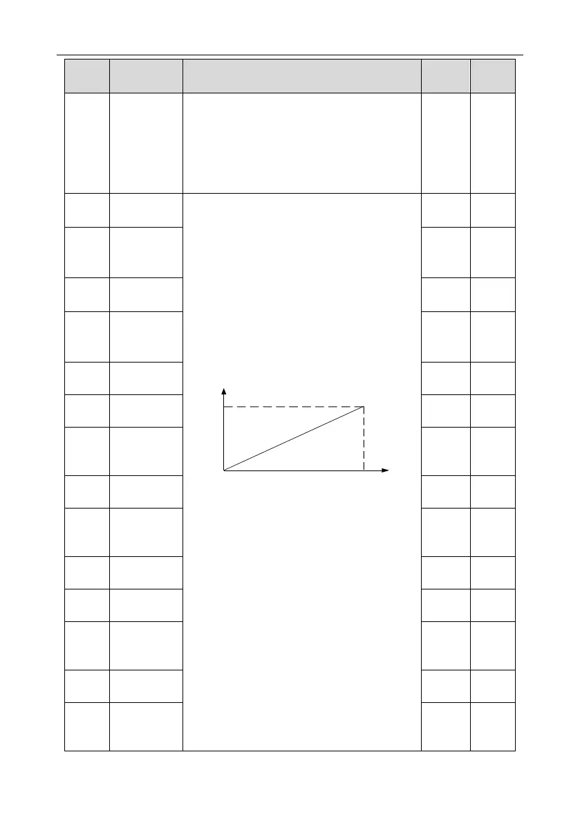
The above function codes define the relative
relationship between the output value and analog
output. When the output value exceeds the range
of set maximum or minimum output, it will count
according to the low-limit or upper-limit output.
When the analog output is current output, 1mA
equals to 0.5V.
In different cases, the corresponding analog
output of 100% of the output value is different. For
details, see section 7.10 PID control.
Setting range of P06.17: -100.0%–P06.19
Setting range of P06.18: 0.00V–10.00V
Setting range of P06.19: P06.17–100.0%
Setting range of P06.20: 0.00V–10.00V
Setting range of P06.21: 0.000s–10.000s
Setting range of P06.22: 0.0%–P06.24
Setting range of P06.23: 0.00V–10.00V
Setting range of P06.24: P06.22–100.0%
Setting range of P06.25: 0.00V–10.00V
Setting range of P06.26: 0.000s–10.000s
Setting range of P06.27: 0.000s–10.000s
Setting range of P06.28: 0.00–50.00kHz
Setting range of P06.29: P06.27–100.0%
Setting range of P06.30: 0.00–50.00kHz
Setting range of P06.31: 0.000s–10.000s
Corresponding
AO1 output to
the lower limit
Upper limit of
AO1 output
Corresponding
AO1 output to
the upper limit
Lower limit of
AO2 output
Corresponding
AO2 output to
the lower limit
Upper limit of
AO2 output
Corresponding
AO2 output to
the upper limit
Lower limit of
HDO output
Corresponding
HDO output to
the lower limit
Upper limit of
HDO output
Corresponding
HDO output to
the upper limit

 Loading...


