Goodrive350-19 series VFD Commissioning
- 79 -
Torque setting mode
selection
0x00–0x11
Ones: HDIA input type
0: HDIA is high-speed pulse input
1: HDIA is digital input
Tens: HDIB input type
0: HDIB is high-speed pulse input
1: HDIB is digital input
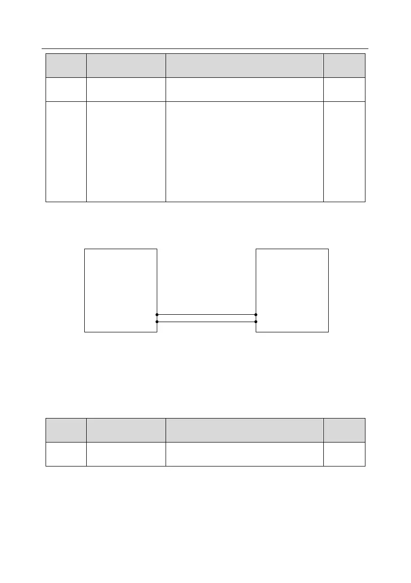
B. Using the VFD analog input terminal (for example, AI1) and analog output terminal (for
example, AO1) to implement simplified master/slave control
The wiring diagram is as follows:
GD350-19 VFD
GD350-19 VFD
Master Slave
GND
GND
AO1
AI1
1. Terminal master/slave mode a
The master adopts the speed control mode and sends the ramp frequency to the slave AI1 terminal
through the AO1 terminal. The slave adopts the speed control mode and the frequency reference is
set by the AI1 terminal. Then, adjust reduction ratio of droop control P08.30 of the salve to meet
power balance.
Master parameters:
0–47
2: Ramp reference frequency

 Loading...

