11
Chapter 1: Assembly & Set-up
Step 2: Connect the cutter to the PC
1. Insert the power cord into the power outlet on the cutter, then
plug it into a wall socket or power strip (Figure 6).
2. Connect the serial cable supplied in the
Accessory Kit to the
cutter.
3. Verify that the cutter is positioned at least 9
inches away from the wall or other objects,
then turn the cutter power on. The Table
will move backward and the carriage to the
right. Wait for the keypad light to turn red,
indicating that the cutter has nished initial-
izing.
4. Connect the serial cable to the serial port
on the computer. Use a 9-25 pin adapter if
required.
5. The cable conguration between the cutter
and computer should resemble the photo in
Figure 7.
6. Turn the computer power on.
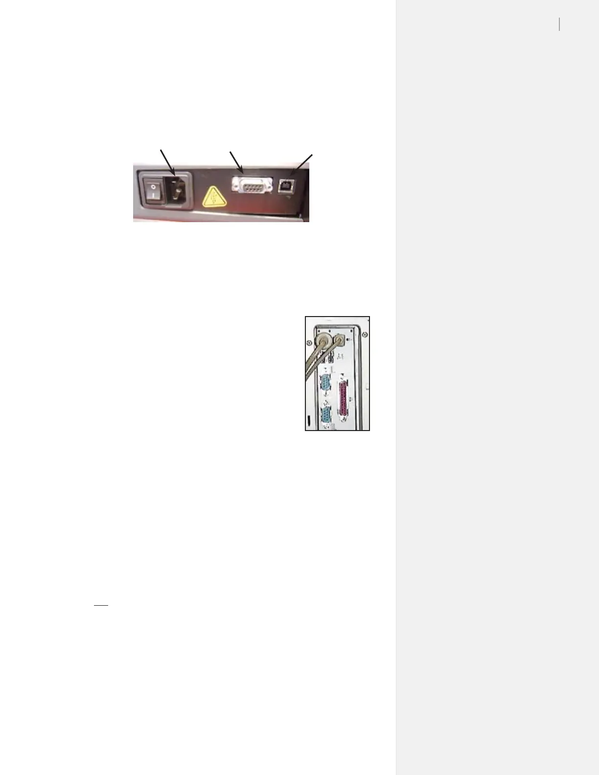
Figure 6. Locations of the power cord outlet, serial port and USB port on the rear
panel of the cutter.
Power cord
outlet
Plotter serial port
(9-pin female)
Plotter USB
port
Figure 7. Rear
view of the com-
puter parallel and
serial ports.
Step 3: Install and adhesive sheet
1. Check the light on the cutter keypad and press Start/Stop if it is
not red. Use the Arrow keys on the keypad to move the Table
all the way forward.
2. If the tray is installed in the Table, loosen the thumb nuts and
remove the tray by lifting up in the front and pulling forward.
Place the tray on a stable surface.
3. Choose an Adhesive Sheet (and backing material, if required)
that are appropriate for the material you plan to cut. (See Fig-
ure 8 to identify proper sheet and backing types. More infor-
mation about choosing Adhesive Sheets is also located in the
300/350HF System User Guide.)
 Loading...