PART 8: ELECTRICAL/LIGHTING TESTING
The Alpha MUTT
®
is microprocessor controlled and features a special diagnostic firmware, designed to
seamlessly integrate with your preferred methods of testing. The tester will power the selected electrical
circuits and instantly alert you to any signs of a faulty condition. To properly utilize the diagnostic
features, a complete scan of the trailer’s electrical system should be performed at the front of the
trailer using the Alpha MUTT
®
prior to a walk-around inspection. If any wiring faults are present, the
tester will blink or sound, alerting you to the issue. Only a one-time, walk-around/visual inspection is
needed to confirm that each individual light bulb is properly illuminating.
8.1 Pretest Checklist
The pretesting checklist should always be completed prior to using the Alpha MUTT
®
.
Tester Placement
• Secure Alpha MUTT
®
to workspace.
• Chock trailer wheels to avoid rolling before testing brakes.
Maintain Connectors
Dielectric grease should be used on all connections to avoid corrosion. If a bad connection exists at the
terminal junction, you may get an erroneous reading and the tester will not work properly.
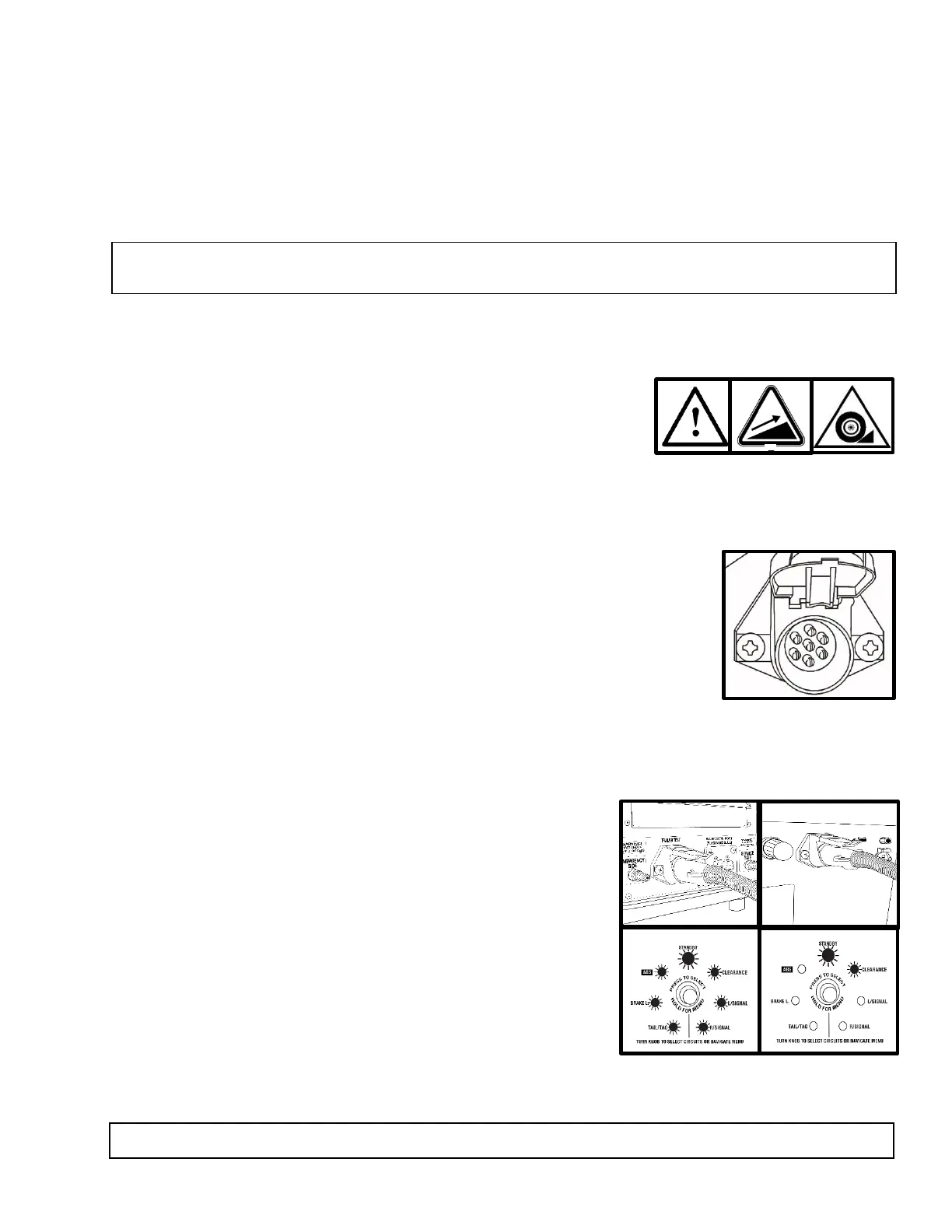
• Make sure you have a solid connection in the socket.
• Be certain the 7 pins in each plug are clean and spread to the proper size.
• Always check the connector pins on the tester for proper expansion. Over
time, the pins may bend in slightly resulting in a poor connection between
the connector and the cable ends. A flat head screwdriver can be used to
expand the pins until a tight connection is made.
Cable Testing Procedure
The Alpha MUTT
®
has a unique feature to test 7-way round pin cables for continuity. The cable testing
feature can be used to test a tractor’s cable or the supplied 7-way cable. All cables should be tested prior
to operation.
• Insert each end of the cable into both connectors on the
tester. Be sure to push the cable ends in firmly until they
reach the bottom of the connector.
• Turn Power Source switch to a desired power supply.
• The green lights around the Circuit Control knob will blink
and disappear one at a time until only the Ground Integrity
indicator remains solid green. Once the initial check has
been performed, poor cable conditions will be shown by a
blinking light for the problem circuit.
• If the cable has an open circuit or continuity problem, the
corresponding circuit will flash repeatedly.
• Further testing can be performed by selecting each circuit
individually via the Circuit Control knob or remote. When an open circuit is detected, the LED for
the circuit will flash and an audible alert will be heard.
NOTE: Some advanced functions may not be listed on the face panel, so it’s important to read the
manual in its entirety to ensure that you are getting the full use of this diagnostic system.
WARNING: Always check that the 7 pins in the plug are clean and spread to the proper size.