Iridium Communications, Inc. Information Contained in this Guide
Iridium 9523 Product Developers’ Guide is Subject to Change Without Notice
Revision 2.6
Iridium Communications, Inc. Distribution of Guide Restricted
Proprietary & Confidential Information Page 17 of 115 to Product Developers
Only
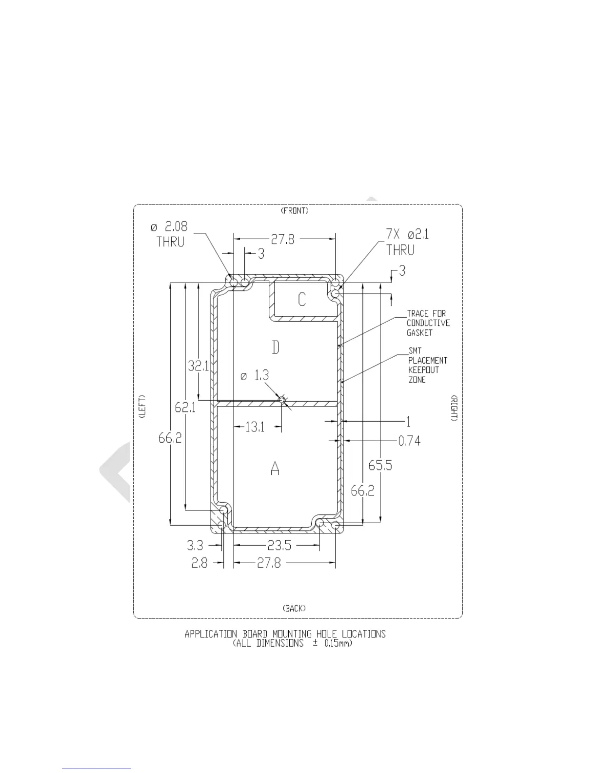
The FA board must provide a sufficient margin free of conductive elements around the 9523 perimeter in
order to avoid electrical shorts with the 9523. This is indicated by the ‘SMT Placement Keepout Zone’.
Partner solutions must be provide sufficient clearance above the conductive capacitors and shield can on
the top of the 9523 to prevent an electrical short.
Figure 4: Mounting location dimensions and layout
(Dimensions in millimeters)