Iridium Communications, Inc. Information Contained in this Guide
Iridium 9523 Product Developers’ Guide is Subject to Change Without Notice
Revision 2.6
Iridium Communications, Inc. Distribution of Guide Restricted
Proprietary & Confidential Information Page 30 of 115 to Product Developers
Only
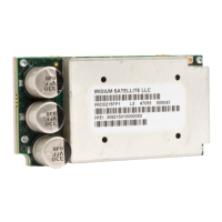
4 RF Interface
This section describes the physical characteristics of the RF connector and specifications of the RF
Interface.
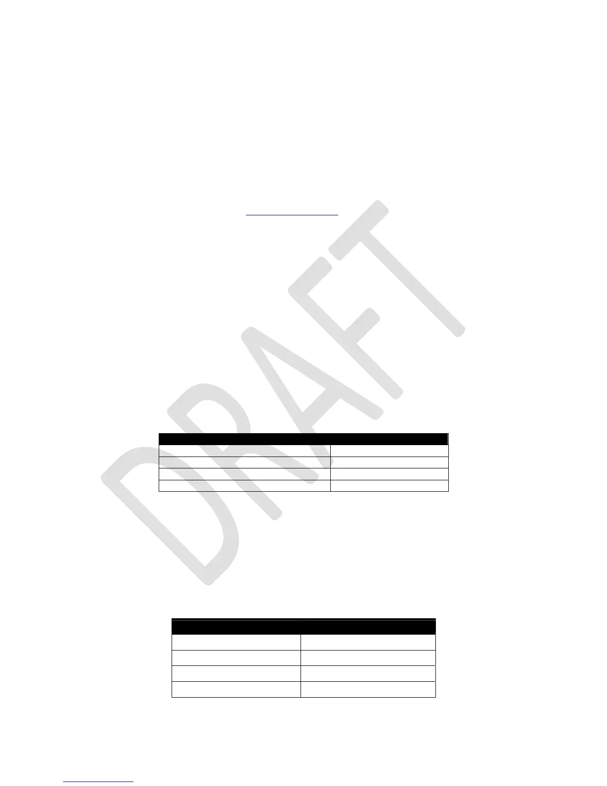
4.1 RF Connector Type
The RF connector on the Iridium 9523 is an I-PEX part number 20314-001E-01, from their MHF product
range. When mating to the Iridium 9523 RF connector, use a suitable plug from the MHF (20308) or
MHFII (20312) ranges.
Additional information can be found at: http://www.i-pex.com
Note that the RF connector on the Iridium 9523 is not mounted directly to the FA board along with the
user interface connector. It must be attached to the FA board through a coaxial cable.
Note that for safety reasons, the RF connector on the Iridium 9523 should not be directly connected to an
external antenna cable or cable distribution system. Paragraph 7.3 of EN60950-1:2006 safety standard
requires that users are protected against high voltages that might appear on these cables. This can be
achieved either by inserting a high-voltage isolating capacitor in series with the signal or by grounding the
shield of the coaxial cable. The I-PEX connector has limited voltage capacity; therefore protection needs
to be provided on the FA board. Developers are encouraged to review the EN60950-1:2006 standard for
additional details.
4.1.1 Antenna Characteristics
The Iridium 9523 should be connected to a certified Iridium-band antenna with the following antenna
connector characteristics as described in Table 12.
Table 12: Antenna Characteristics
Parameter Value
Impedance 50 Ohms nominal
Gain (maximum) 3 dBi
Polarization RHCP
VSWR (maximum operational) 1.5 : 1
Existing qualified Iridium antennas may be used. (i.e. antennas designed and certified for the 9601, 9602,
9522, 9522A and 9522B) in conjunction with suitable protection circuitry.
4.2 RF Interface Specifications
The RF interface requirements for the Iridium 9523 are summarized in Table 13 below.
Table 13: General RF Parameters
Parameter Value
Frequency Range 1616 MHz to 1626.5 MHz
Duplexing Method TDD (Time Domain Duplex)
Input/Output Impedance 50Ω
Multiplexing Method TDMA/FDMA