Iridium Communications, Inc. Information Contained in this Guide
Iridium 9523 Product Developers’ Guide is Subject to Change Without Notice
Revision 2.6
Iridium Communications, Inc. Distribution of Guide Restricted
Proprietary & Confidential Information Page 20 of 115 to Product Developers
Only
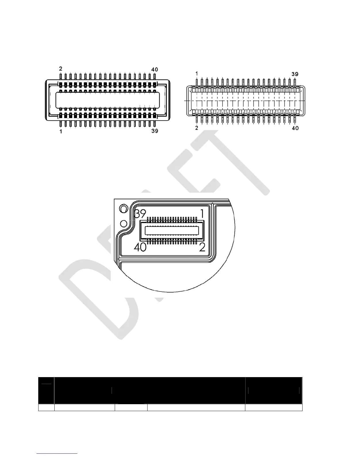
Figure 5: Pin numbering scheme for User Connector
Molex 54102-0404 on Iridium 9523: Molex 53885-0408 on FA PCB:
Error! Reference source not found. provides a reference for the pin designation and shows the connector’s
location and rotation with respect to the corner of the Iridium 9523 board. This view is for illustrative
purposes only. This view designation is when looking into the user connector towards the Iridium 9523.
Figure 6: User Connector Pin Number Designation
3.1.2 User Connector Pin Allocation
The user connector is a 2-row 40-way header. Individual pin assignments are shown in Table 6 and the
limits for the digital signals are listed in Table 7. Multiple supply grounds are provided and all supply rails
and supply grounds are required to be connected to the power supply in order to limit the current on any
one pin.
Table 6: User Connector Pin Allocation
Pin
No.
Signal Name
Signal
direction
(WRT
modem)
Signal function Signal group
1 CODEC_PCMCLK Out Clock PCM audio port 1