13 of 48IPC/IPC-N, 14-013, REV. D
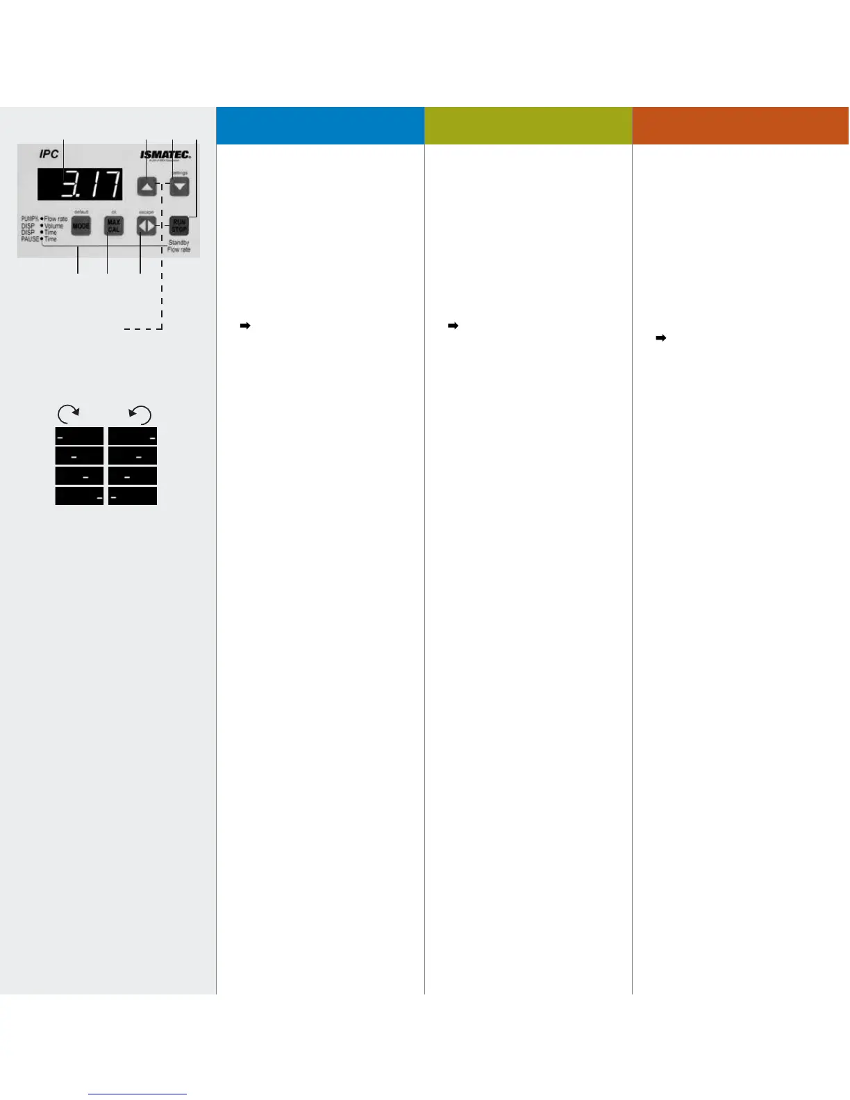
1. Digitale LED-Anzeige
2. Wert erhöhen
3. – Wert reduzieren
– settings*
4. RUN/STOP
– Startet bzw. stoppt die Pumpe
(die Drehrichtung wird mit laufendem
Strich kurz angezeigt).
– Unterbricht Dosierung bzw. setzt
diese fort (Seiten 22/25).
Die Funktion Start/Stopp
kann auch über einen externen
Impulsgeber ausgelöst werden, wie
z.B. Fußschalter oder Dosierhandgriff
(Zubehör Seite 42).
4. a. Kombination mit Pause•Time
und RUN/STOP = Standby-Funktion
(Pumpe pumpt mit 1% der
max. Fließrate).
5. MAX/CAL
– Max. Drehzahl in
Betriebsart PUMP•rpm und
PUMP%•Flow rate (ideal zum Füllen
oder Entleeren der Schläuche; Taste
bei laufender Pumpe gedrückt halten)
– Kalibriertaste für Fließrate bzw.
Dosiervolumen (Seiten 19 und 23).
– ok*
6. Drehrichtung
– wechselt die Drehrichtung
(Beim Ändern der Drehrich-tung
bzw. Starten der Pumpe wird die
Drehrichtung mittels laufendem Strich
im Display kurz angezeigt).
– Bricht angefangene Dosie-rung ab
(Seiten 22 und 25)
– escape*
* = Grundeinstellungen S. 15–17
1. Digital LED display
2. Increase value
3. – Reduce value
– settings*
4. RUN/STOP
– Starts and stops the pump (the
rotation direction is briefly indicated
with a running dash).
– Interrupts and continues a
dispensing cycle (Pages 22/25).
The function Start/Stop can also
be triggered by an external device
such as a footswitch or hand dispenser
(accessories on Page 42).
4. a. Combination with Pause•Time and
RUN/STOP = stand-by function (pump
runs at 1% of the max. flow rate).
5. MAX/CAL
– Max. speed in the modes
PUMP•rpm and PUMP%•
Flow rate (ideal for filling or emptying
the tubes; keep the MAX key pressed
down while the pump is running).
– Calibrating key for the flow rate or
dispensing volume (Pages 19 and 23).
– ok*
6. Rotation direction
– Changes the rotation direction (the
rotation direction is briefly indicated in
the display with a running dash).
– Stops an interrupted dispensing
cycle for good (Pages 22 and 25).
– escape*
* = Basic settings Pages 15–17
1. Affichage LED
2. Augmenter la valeur
3. – Réduire la valeur
– settings*
4. RUN/STOP
– Mettre en route ou arrêter
la pompe (le sens de rotation est
simplement indiqué par un tiret
qui se déplace).
– Interrompt/poursuit une
distribution (Pages 22/25).
La fonction Start/Stop peut
également être lancée au moyen d’un
appareil externe comme une pédale
de commande ou une poignée de
distribution(accessoires Page 42).
4. a. Combinaison avec Pause•Time
et RUN/STOP = fonctionnement en
stand-by (pompe fonctionne à 1% du
débit max.)
5. MAX/CAL
– Nombre de tours maximal dans les
modes PUMP•rpm et PUMP%•Flow
rate (pour un remplissage et une
vidange rapides du système maintenir
la touche MAX /CAL enfoncée lorsque
la pompe fonctionne).
– Touche de calibrage pour le débit
ou le volume de distribution
(Pages 19 et 23).
– ok*
6. Sense de rotation
– Change le sens de rotation.
(En changeant le sens de rotation
ou en lançant la pompe, le sens de
rotation est indiqué sur l’affichage
avec un tiret défilant).
– Interrompt une distribution
commencée (Pages 22 et 25)
– escape*
* = Réglages de base Pages 15–17
41 2
7
3
* = Grundeinstellungen
* = Basic settings
* = Réglages de base
(Seiten/Pages 15–17)
65
Tableau de commandeOperating panelBedienungspanel