9 of 48IPC/IPC-N, 14-013, REV. D
1 2
3 4 5
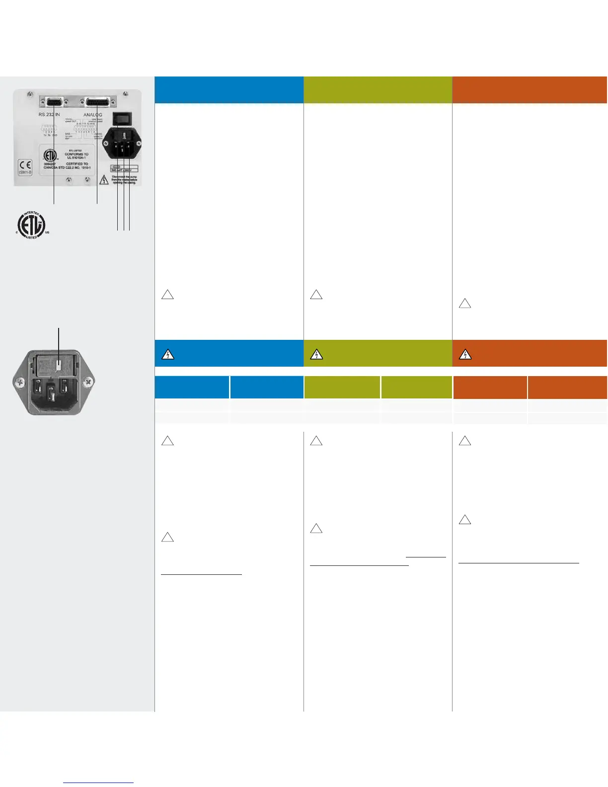
1. RS232 IN (Eingang)
2. Analog-Schnittstelle
Eingänge für:
– Drehzahlsteuerung
0–5 V oder 0–10 V, bzw.
0–20 mA oder 4–20 mA
– Start/Stopp
– Drehrichtun
Ausgänge für:
– Drehzahl 0–10 V
DC
oder 0/10.9 kHz
3. Netzschalter ein/aus
4. Sicherungshalter mit
Spannungswähler 115/230 V
5. Netzbuchse
Detaillierte Angaben zur Analog-
Schnittstelle finden Sie auf Seite 33
1. RS232 IN
2. Analog interface
input for:
– speed control
0–5 V or 0–10 V, and
0–20 mA or 4–20 mA
– Run/Stop
– Rotation direction
output for:
– speed 0–10 VDC
or 0/10.9 kHz
3. Mains switch (ON/OFF)
4. Fuse-holder with voltage
selector 115/230 V
5. Mains socket
For further details on the analog
interface please refer to Page 33.
1. RS232 IN (entrée)
2. Interface analogique
Entrée:
– commande de vitesse
0–5 V ou 0–10 V, resp.
0–20 mA ou 4–20mA
– marche/arrêt
– sens de rotation
Sortie:
– vitesse 0–10 V
CC
ou 0/10.9 kHz
3. Commutateur principal
(marche/arrêt)
4. Porte-fusibles avec sélecteur de
tension 115/230 V
5. Prise d’alimentation
Pour l'utilisation de l'interface
analogique voir Page 33.
Fenster für Spannungswahlanzeige
Wenn nötig, müssen die Einstellung
geändert werden.
Window for voltage setting
If necessary, the voltage setting
must be changed.
Fenêtre de réglage de la tension
Si nécessaire, modifiez la tension.
Tableau arrièreRear panelGeräterückwand
Tension d‘alimentation
Avant la mise en service
Contrôlez si la tension indiquée dans la fenêtre
du porte-fusibles correspond à la tension de
votre réseau local.
Si nécessaire, modifiez la tension et
remplacez les deux fusibles correspondants.
Prise/câble d’alimentation
N’employer que le câble d’alimentation
d’origine.
La prise doit être raccordée à la terre
(contact conducteur de protection).
Mains voltage
Before starting-up
Check if the voltage setting visible
in the window of the fuse-holder
complies with your local mains voltage.
If necessary, the voltage setting
must be changed and the 2 fuses
must be replaced.
Socket/Power cord
Use exclusively the original power cord
supplied with the pump. The socket must
be connected to earth ground (protective
conductor contact).
Netzspannung
Vor der Inbetriebnahme
Prüfen Sie, ob die Spannungs-
wahlanzeige im Fenster des
Sicherungshalters der Netzspannung
Ihres Landes entspricht.
Wenn nötig, müssen die Einstel-lung
geändert und die 2 Siche-rungen
ausgetauscht werden.
Steckdose/Netzkabel
Verwenden Sie ausschließlich das
mitgelieferte Originalkabel. Die
Steckdose muss geerdet sein
(Schutzleiterkontakt).
Netz-anschluss Sicherung
220–240 V
AC
50/60 Hz
2 x T500mAL/250V
110–120 V
AC
50/60 Hz
2 x T500mAL/250V
Mains voltage Fuse rating
220–240 V
AC
50/60 Hz
2 x T500mAL/250V
110–120 V
AC
50/60 Hz 2 x T500mAL/250V
Tension d‘
alimentation
Fusibles
de sécurité
220–240 V
CA
50/60 Hz 2 x T500mAL/250V
110–120 V
CA
50/60 Hz 2 x T500mAL/250V