Function and Features
Copyright ©ITECH Electronics Co., Ltd. 30
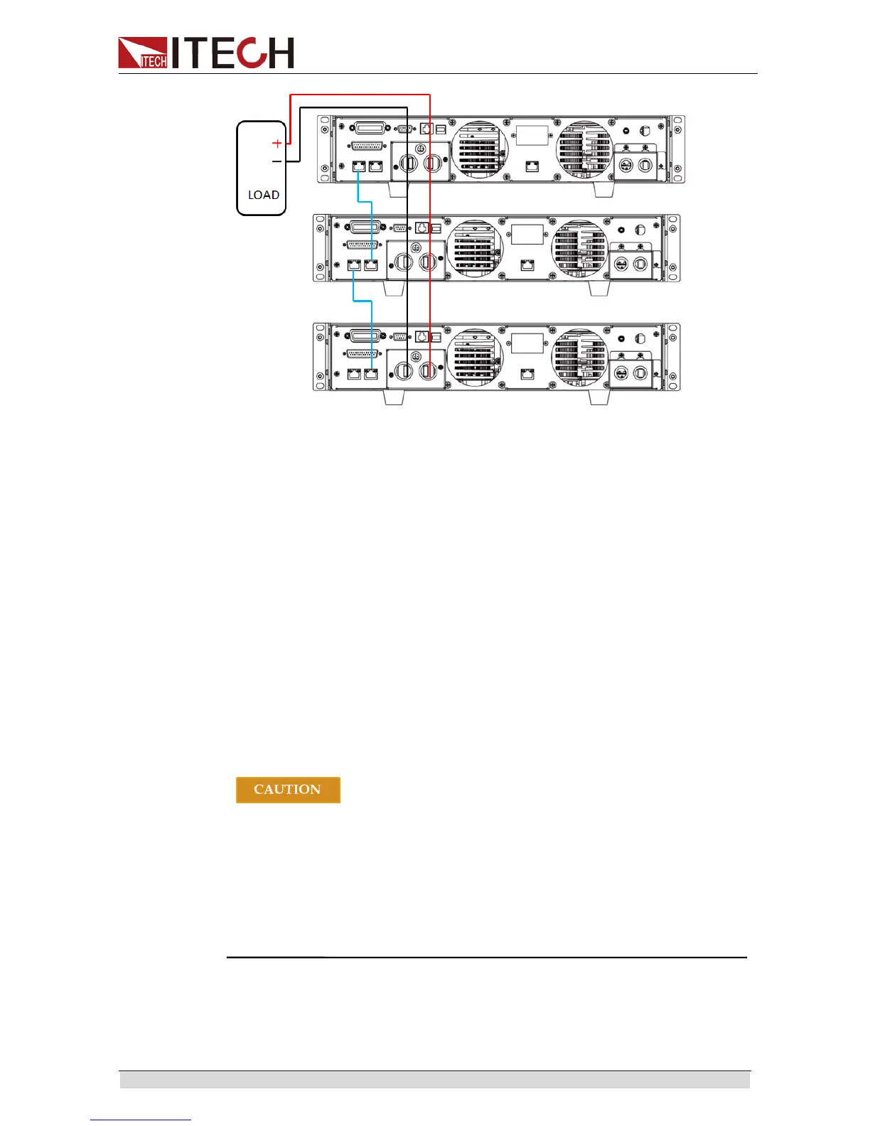
The master-slave connection for configuring 3 pcs power supplies is as follows:
1. Configure one power supply as the Master and the other power supplies as
Slave. Press the composite key
[Shift]+[P-set](Menu) to enter the System
Menu.
Press the Right key to select “ CONFIG” and press
[Enter] to enter the
Configuring Menu.
2. Press the Right key to select “ Parallel” and press [Enter] for parallel
setting.
Single: Single mode.
Slave: Salve mode.
Master: Master mode. If Master mode is selected, you need to set the
number of Salves for the Master.
Mount: total number of instruments in parallel. For example, Mount=3.
3. After setting of host and slave, switch off the power supply. Connect the
networking.
Connect the networking as shown above. Please connect the network after
parallel setup. Otherwise, at start up, the power supply will detect parallel setup
fault and fail to start up.
When connecting the system bus, please note the built-in terminal
matching resistance at the rear panel. If the resistance is removed,
the instrument may not work properly. The user can install the
terminal matching resistance on the Input end of the first system bus
and the Output end of the last system bus.
The system bus interface is not isolated from the output electrode.
After power on, it is not allowed to insert or pull out the bus and
terminal matching resistance.
3.17 Rear Panel Terminal Functions
If the tested instrument consumes large current, a large voltage drop will be
detected in connection line between tested instrument and power supply