System-Related Functions
Copyright ©ITECH Electronic Co., Ltd. 57
how to connect and how to use.
When the voltage setting is controlled through the analog interface, the external
voltage is connected to program the voltage value between 0 and full scale(AC
mode) according to the voltage ratio. When parallel machine operation, can be
controlled through the host analog interface.
For example, analog control AC range of 0~350V voltage, when the U ratio is
set to 50V/1V and analog signal voltage is set to 6V, the instrument output
voltage is set to 6*50=300V.
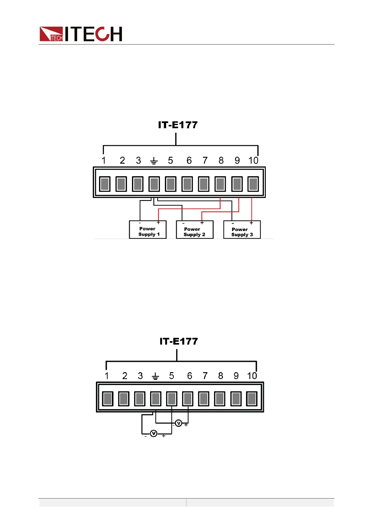
Voltage and current monitoring
Through the analog interface, the existing output voltage/current can be
monitored. Connect a digital voltmeter or oscilloscope between pin 5
(V_Monitor), pin 6 (I_Monitor) and ground wire 4 (GND) of the analog interface.
The voltage reading corresponds to the power voltage and current output
between
negative full range and positive full scale.
Under single phase mode, the phase cannot be set, under three phase mode,
the voltage and current of phase can be set in menu.
The wiring diagram is shown in the figure below.

 Loading...